BWR Break Modeling
Source
BWR Modeling Guidance — Break Modeling (DEG, SEG, and Split Breaks).
Overview
This section provides guidance on modeling BWR pipe breaks in TRACE, covering three break types:
- Double Ended Guillotine (DEG) — LBLOCA, typically on the recirculation line
- Single Ended Guillotine (SEG) — IBLOCA/SBLOCA on injection lines connected to RPV
- Split Break — IBLOCA/SBLOCA with break flow area less than full pipe area
The guidance is applicable to GE BWR/3, BWR/4, BWR/5, and BWR/6.
Required Inputs
- Break type, location, flow area, and orientation
- Assumed initial containment conditions (temperature, pressure)
- Injection line geometry (length, orientation, ID) — for SEG breaks
Break Pipe Nodalization Criteria
For all break types, the control volumes within 2.0 meters of the break must be renodalized to accurately predict break flow, pressure gradients, and void fraction gradients for choked flow:
Break-Adjacent Cell Sizing
- The cell adjacent to the break must have 0.25 ≤ L/D ≤ 3.0 (preferred: 1.0 < L/D < 2.0)
- Volumes within 2.0 m of the break should gradually increase — double each successive cell volume until approaching the unmodified model cell volume
- 10:1 adjacent cell volume ratio must be maintained
DEG Break Modeling
Steady State
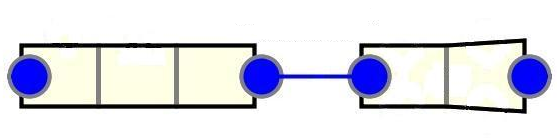
The pipe containing the break is split into two PIPE/VALVE components joined at the break location. Each component is renodalized per the criteria above.
Transient
Two BREAK components are attached to the two pipe ends. Changes are made in the restart file, not the steady-state model.
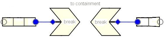
Pipe component updates (transient):
| Parameter | Value |
|---|---|
| NFF at break edges | 0 (significant FA change to break) |
| KFAC (vessel-side break edge) | (1−β²)² ≈ 1.0 (sudden expansion to containment) |
| KFAC (loop-side break edge) | 0.5·(1−β²) ≈ 0.5 (sudden contraction from containment) |
| KFACR | Reverse of above |
| ICFLG at break edges | 1 (choked flow expected) |
Injection Line SEG Break Modeling
Steady State
An injection line stub PIPE component (minimum 2 cells) is added to the steady-state model, connecting the RPV to a BREAK component.
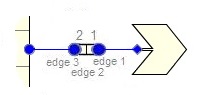
Injection Line Stub — PIPE (≥2 cells)
Cell Layout:
- Last cell = sparger ring (if applicable): DX = (θinjection/360°) · π · Rsparger
- Remaining cells = injection line length, nodalized per break criteria
Volume:
- Sparger ring cell: VOL = 2·DX · π/4 · ID²sparger
- Pipe cells: VOL = DX · π/4 · ID²injection line
Edge Geometry:
| Edge | FA | HD |
|---|---|---|
| First (break) | 0.0 (steady-state — opened in transient) | IDinjection line |
| Interior | π/4 · ID²injection line | IDinjection line |
| Last (sparger nozzles) | Total sparger nozzle flow area | ID of one sparger nozzle |
Friction:
- NFF = 0 at all edges (exempt from normal nodalization criteria)
- KFAClast edge = 1.0 (contraction + infinite expansion through sparger)
- KFACRlast edge = 0.5
- ICFLGedge1 = 1; ICFLGlast edge = 2 (allows critical flow multipliers)
Initial Conditions:
| Parameter | LPCI stub | Core spray stub |
|---|---|---|
| TL | Tsat − ΔTsubcooling | Tsat |
| ALPN | 0.0 (below water level) | 1.0 (above water level) |
| VL, VV | 0.0 (no flow during SS) | 0.0 |
- ICHF = 1 (critical heat flux modeled)
Transient
Open the break by setting FAedge1 = π/4 · ID²injection line
Split Break Modeling
Steady State
The pipe remains as a single component, renodalized per break criteria.

Transient
A BREAK component is connected via a SJC (single junction component) attached by side junction to the pipe at the break location.
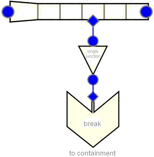
Pipe component updates:
- NSIDES = 1 (add side junction at break cell)
- THETA = 90° (perpendicular to pipe)
- IENTRN = 1 (tee offtake model on)
SJC setup:
| Parameter | Value |
|---|---|
| FA | Desired break flow area |
| HD | √(4·FA/π) — assuming circular break |
| NFF | 0 |
| KFAC | 60 fT + (1−β²)² ≈ 60 fT + 1.0 (tee branch + expansion) |
| KFACR | 60 fT + 0.5·(1−β²) ≈ 60 fT + 0.5 (tee branch + contraction) |
| ICFLG | 2 (allows critical flow multipliers) |
| CCFL | Not applied |
| VL, VV | 0.0 (break not yet initiated) |
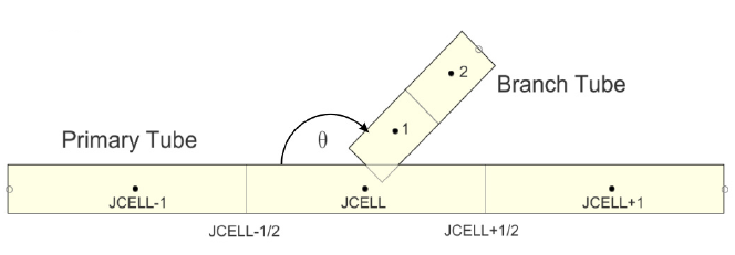
SJC orientation depends on break position:
| Break Position | Angle | GRAV |
|---|---|---|
| Top of pipe | +π/2 | +1.0 |
| Bottom of pipe | −π/2 | −1.0 |
| Side of pipe | 0.0 | 0.0 |
SBLOCA Break Sizing
For SBLOCA analyses, the limiting break size is typically just below the threshold where the LOCA progression changes to LBLOCA-like behavior. Range the break flow area to determine the most limiting PCT. Break areas will not exceed 2× the pipe flow area (DEG equivalent).
BREAK Component Inputs (All Break Types)
| Parameter | IBTY = 7 (CONTAN coupled) | IBTY = 0 (constant P) |
|---|---|---|
| ISAT | 0 (enter liquid/gas temp) | 3 (set to Tsat) |
| IOFF | 0 (last interp held constant) | 0 |
| DXIN | DX of upstream cell | 10⁻⁶ m |
| VOLIN | VOL of upstream cell | 10⁶ m³ |
| ALPN | 1.0 | 1.0 |
| TIN | Containment temperature | Containment temperature |
| PIN | Initial containment pressure | Min containment pressure (or 14.5 psia) |
| PAIN | Pcontainment − Psat(TIN) | Pcontainment |
| ADJPRESS | False | False |
| RBMX | 10²⁰ Pa/s | 10²⁰ Pa/s |
| PSCL | 1.0 | 1.0 |
IBTY = 7 specific:
| Parameter | Value |
|---|---|
| COMPID | Drywell CONTAN component ID |
| Compartment Region | Vapor Space (positive COMPID) |
| BDSPRAY | 1.0 (full thermal equilibrium) |
| BDCOND | 1.0 (full thermal equilibrium) |
Break tables, rate factor tables, break signal, and break trip are not used with IBTY = 0 or 7.
Cross-References
- Recirculation Lines — Recirculation line break locations
- Containment — CONTAN component for break backpressure
- Reactor Vessel — RPV injection line connections
This page faithfully extracts break modeling guidance from the BWR Modeling Guidance. Three break types are covered: DEG (two BREAK components on split pipe), injection line SEG (stub PIPE with opened first edge), and split break (SJC + BREAK via side junction with tee offtake model). Break-adjacent cells require L/D between 0.25–3.0 with 2× volume grading within 2 m of break.