BWR Steam & Feedwater System Modeling
Source
BWR Modeling Guidance — Steam & Feedwater System Modeling.
Overview
This section provides guidance on modeling the BWR steam network and feedwater system in TRACE, covering all components from the RPV steam outlet to the turbine/condenser boundary conditions, plus the feedwater line back to the RPV. The guidance is applicable to:
- GE BWR/3, BWR/4, BWR/5, and BWR/6
Required Inputs
- MSL geometry (ID, length or volume), material properties, wall thicknesses
- MSL flow restrictor geometry (Venturi throat ID, inlet/outlet IDs, length)
- Equalizing header geometry
- MSIV seat IDs, locations, loss coefficients, closing times, response delays
- SRV line geometry, rated flow capacities/pressures, seat IDs, loss coefficients, opening/closing times/setpoints, ADS response parameters
- Turbine inlet/bypass line geometry
- TCV/TSV geometry and opening/closing characteristics
- FW line geometry, FW sparger geometry (ID, length, radius of curvature), FW injection flow area
- Condenser and wetwell nominal conditions (pressure, temperature)
- System nominal pressure, total rated steam/FW flow
Component Summary
The steam network typically consists of:
| Component | Type | Typical NCELLS | Notes |
|---|---|---|---|
| MSL/MSIV (×3) | VALVE | 1 + L/(8·ID), rounded up | Two individual + one lumped pair; DX/HD ≤ 8 for pressure propagation |
| SRV banks (×9) | VALVE | 0 or 2 | Three per MSL; zero-cell (config a) or 2-cell (config b for ADS) |
| SRV/ADS BREAKs | BREAK | — | Connected to wetwell CONTAN |
| Turbine inlet/TCV | VALVE | L/(8·ID) + 1 | Cell 1 = equalizing header; TSV/TCV lumped |
| Turbine bypass (TBV) | VALVE | 0 | Side-junction connected, zero-cell |
| Turbine BREAK | BREAK | — | Turbine backpressure BC |
| Condenser BREAK(s) | BREAK | — | Condenser backpressure BC |
| Feedwater line | PIPE | 3–5 typical | From FW BC to RPV |
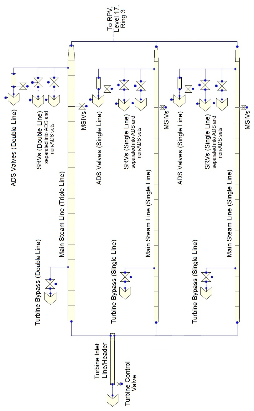
MSL Nodalization
The DX/HD ratio of ~8 is based on recent NRC experience with turbine trip transients where pressure propagation through the steam lines is important. For LOCA analyses where secondary side effects are less important, coarser nodalization (DX/HD ≤ 30) may be used to save computational time. For MSL break scenarios, break nodalization guidance applies.
Main Steam Line / MSIV — VALVE

Key features:
- 4 physical MSLs → 3 VALVE components (2 individual + 1 lumped pair)
- Average MSL length/volume used to facilitate lumping
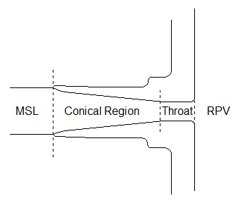
- Cell 1 models MSL flow restrictor (Venturi — frustum geometry)
- MSIV modeled as valve at appropriate edge (IVTY=3)
- MSL connects to equalizing header at outlet
- SRV/ADS components attach via side junctions
MSL/MSIV valve inputs: Same IVTY=3/INTLOSSOFF=1/KOPEN pattern as recirculation valves. MSIV-specific: FAVLVE=1.0 (initially open), VTB1 closing table uses MSIV closing time with response delay.
Safety Relief Valves / ADS — VALVE
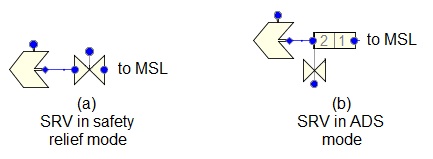
Configuration:
- 9 SRV components per MSL arrangement (3 per MSL component)
- 3 pairs use config (a) — zero-cell side-junction VALVE
- Last set uses config (b) — 2-cell VALVE for ADS function
- Each SRV/ADS VALVE connects to a wetwell BREAK (IBTY=7 CONTAN)
SRV valve inputs: IVTY=3, trip uses 4-setpoint hysteresis (same pattern as PWR PORV/SRV):
- Setpoint Range Type: 3 [ON(For) || OFF || On(Rev)]
- SETP1 = closing pressure, SETP4 = opening pressure
- SETP2 = average(SETP1,SETP4) − 0.1%, SETP3 = average(SETP1,SETP4)
- SRV banks have different setpoints reflecting the plant stagger
ADS trip: Separate trip logic with specific ADS initiation criteria (low water level + timer).
SRV/ADS BREAK Components
Connected to wetwell CONTAN. Key parameters:
- IBTY = 7 (CONTAN coupled), COMPID = wetwell component ID
- Compartment Region = Liquid Space (negative COMPID — SRVs discharge below suppression pool surface)
- ISAT = 0, DXIN/VOLIN match upstream cell, BDCOND = plant-specific
Turbine Inlet / TCV — VALVE
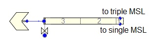
- Cell 1 = equalizing header (all MSLs feed in)
- TSV and TCV lumped at TCV location
- NCELLS = L/(8·ID) + 1, DX/HD ≤ 8
- Valve at last edge; IVTY=3
Turbine BREAK
- IBTY = 0 (constant pressure) or IBTY = 1 (pressure table)
- PIN = condenser pressure (for constant) or pressure schedule
- ISAT = 3; ALPN = 1.0; DXIN = 10⁻⁶ m; VOLIN = 10⁶ m³
Turbine Bypass Valve — VALVE (0 cells)

- Zero-cell VALVE, side-junction connected to turbine inlet line or MSL
- May be single bypass line or two (one per MSL), depending on plant
- IVTY=3; trip and table define TBV opening characteristics
Condenser BREAK
Same pattern as turbine BREAK (IBTY=0 at condenser pressure).
Feedwater Line — PIPE
- Models the FW line from the FW regulation boundary condition to the RPV
- Last cell = FW sparger ring (if modeled): DX = (θ/360°) · π · Rsparger
- FW FILL connected upstream; injects at appropriate downcomer elevation
- Typically 3–5 cells; orientation varies with plant-specific routing
Key notes:
- FW line is included primarily for FW line break transients and FW mass inventory
- For non-FW-break transients, the FW line has minimal impact on results
- FW sparger ring volume included as last cell; injection ports as last edge FA
General Notes — All Steam/FW Components
| Parameter | Value |
|---|---|
| ICONC | 0 (no boron in BWR) |
| IPOW | 0 |
| EPSW | Plant-specific or 4.572 × 10⁻⁵ m |
| INTLOSSOFF | 1 (Off) for all VALVE components |
| Use Pipewall | Per heat structure guidance (manually attached HTSTR) |
Steady-State Checklist
Steady-State Verification
- Total steam flow matches rated value
- Steam dome pressure matches nominal
- MSL pressure drop is reasonable
- SRVs are closed during steady state
- TCV is at appropriate position for rated power
- TBVs are closed during steady state
- FW flow matches rated value
- FW temperature is correct
Cross-References
- Steam Separators — Upstream of MSLs
- Reactor Vessel — RPV steam outlet connections
- Containment — SRV/ADS discharge to suppression pool
- Break Modeling — MSL/FW line break nodalization
This page faithfully extracts steam and feedwater system modeling guidance from the BWR Modeling Guidance. The steam network includes 3 MSL/MSIV VALVEs (DX/HD≤8 for pressure propagation), 9 SRV VALVEs (zero-cell + 2-cell ADS variants with 4-setpoint hysteresis trips), turbine inlet/TCV, TBV bypass, and associated BREAK BCs. The FW line is a simple PIPE primarily important for FW line break scenarios.