BWR Steam Separator Modeling
Source
BWR Modeling Guidance — Separator/Dryer Modeling.
Overview
This section provides guidance on modeling BWR steam separators in TRACE using the SEPD component. The dryers are not explicitly modeled as a separate component — their effect on liquid-vapor separation is captured in the separator carryover/carryunder values, and the dryer fluid volume is included as part of the RPV VESSEL free volume. The guidance is applicable to:
- GE BWR/3, BWR/4, BWR/5, and BWR/6
A typical BWR model includes four SEPD components representing separators in Rings 1 and 2 of the RPV (one per azimuthal sector). Separators are lumped together within each region as ideal separator models with realistic carryunder/carryover values that include the combined effect of separators and dryers.
Required Inputs
- Nominal system pressure, feedwater flow rate, core flow rate
- RPV nodalization (cell heights for axial levels)
- Standpipe geometry (length, ID)
- Separator geometry (lengths, ID/OD of all regions, swirl vane volume)
- Separator carryover and carryunder
- Pressure drop across separators
- Loss coefficients for swirl vane and liquid return path
- Total number of separators and fuel assemblies (total and Ring 1)
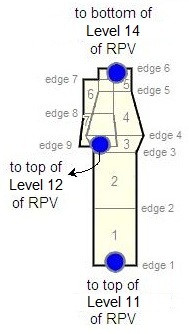
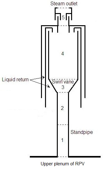
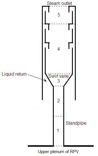
Component Setup — SEPD (5 main cells + 2 side cells, 9 edges)
Initialization:
- Main Tube Length = DZRPV,Level12 + DZRPV,Level13
- Side Tube Length = height from swirl vane inlet bottom to bottom of last separation stage
- NCELL1 = 5 (main tube), NCELL2 = 2 (side tube — liquid return)
- Cosine Theta = −1.0 (downward side tube)
Geometry
Cell Layout
| Cell | DX | Description |
|---|---|---|
| 1, 2 | ½ × Haverage standpipe | Standpipe |
| 3 | Hswirl vane cone | Swirl vane cone |
| 4 | Hmain stage (2-stage) or Hlower two stages (3-stage) | Main separator body |
| 5 | Htop stage | Top stage |
| 6, 7 (side) | ½ × (DZRPV,Level13 − DXcell5) | Liquid return path |
Volume Formulas (per ONE separator)
| Cell | Formula |
|---|---|
| 1, 2 | DX · π/4 · ID²standpipe |
| 3 | π/12 · DX · (ID²standpipe + ID²main sep + IDstandpipe · IDmain sep) − VOLswirl vanes |
| 4 | DX · π/4 · ID²main separator |
| 5 | π/4 · DX · [ID²top stage + (OD²liquid return − ID²liquid return)] |
| 6, 7 | Annular liquid return path volume (see source for 2-stage vs. 3-stage formulas) |
Edge Geometry
| Edge | FA | HD |
|---|---|---|
| 1–3 (standpipe) | π/4 · ID²standpipe | IDstandpipe |
| 4 (main separator) | π/4 · ID²main sep | IDmain sep |
| 5 (separator cap) | π/4 · ID²sep cap | IDsep cap |
| 6 (steam outlet) | π/4 · ID²steam outlet | IDsteam outlet |
| 7, 8 (liquid return — main) | Annular: π/4·(OD²outer − ID²outer + OD²inner − OD²main sep) | 4·FA / (π·perimeter) |
| 9 (liquid return — bottom) | Annular: π/4·(OD²outer − ID²outer + OD²inner − OD²standpipe) | 4·FA / (π·perimeter) |
- CCFL: not applied at any edge (LCCFL = 0)
Orientation
| Edges | GRAV |
|---|---|
| 1–6 (main tube — upward) | +1.0 |
| 7–9 (side tube — downward) | −1.0 |
Initial Conditions
- P = plant-specific or nominal system pressure
- TL, TV = Tsat
- ALPNcells1-5 = plant-specific or 0.70 (main pipe)
- ALPNcells6-7 = plant-specific or 0.0 (liquid return)
- PA = 0.0
Main Pipe Void Fraction
The void fraction in the main pipe cells should not be set to single-phase conditions — this will cause TRACE to switch the special SEPD modeling off and treat the component as a TEE. Use 0.70 if plant-specific values are unknown.
Liquid velocity estimates:
- VLedge6 ≈ 0.0 (all vapor exits top)
- VLedges7-9 = (ṁcore − ṁFW) / (ρliquid · FA)
- VVedges1-5 ≈ VLedges1-5
- VVedge6 = ṁFW / (ρsteam · FAedge6)
- VVedges7-9 ≈ 0.0
Friction
| Edge | NFF | KFAC | KFACR |
|---|---|---|---|
| 1 | 0 | 0.5 (infinite contraction) | 1.0 (infinite expansion) |
| 2–3 | 1 | 0.0 | 0.0 |
| 4 | 0 | Facility value or 0.5 (swirl vane — tune to ΔP) | Same |
| 5 | 0 | 0.5·(1−β²) for 2-stage only | (1−β²) for 2-stage only |
| 6 | 0 | 1.0 (infinite expansion) | 0.5 (infinite contraction) |
| 7 | 0 | Facility value, or 9.5 (from Idelchik 6-27) | Facility value, or 9.7 (from Idelchik 6-28) |
| 8 | 1 | 0.0 | 0.0 |
| 9 | 0 | 1.0 (infinite expansion) | 0.5 (infinite contraction) |
- Edge 5 (2-stage only): β = ID2nd stage / ID1st stage
- ICFLG = 0 at all edges
General Inputs — Separator Parameters
| Parameter | Value |
|---|---|
| ISTAGE | 0 (ideal separator with constant carryover/carryunder) |
| JCELL | 5 (liquid return side tube connects at cell 5) |
| IENTRN | 0 (offtake model off) |
| NDRYR | 0 (dryers included in carryover, modeled in RPV) |
| XCO (carryover) | Plant-specific, or 1.0 × 10⁻³ (net through separator + dryer) |
| XCU (carryunder) | Plant-specific, or 2.5 × 10⁻³ (typical GE separator) |
| ALPSMN | 0.05 (minimum barrel void — avoids oscillation) |
| ALPSMX | 0.9 (maximum barrel void) |
| IPOW | 0; EPSW = plant-specific or 4.572 × 10⁻⁵ m |
| Use Pipewall | False (HTSTR components required for separator walls) |
NSEPS — Number of Separators per Component
Each SEPD component represents separators in one ring/sector:
Carryover/Carryunder Sensitivity
Certain transients can be sensitive to carryover and carryunder fractions. Plant-specific data should be used when available. Using a value of 0.0 is not recommended because it leads to non-physical dynamic level response behavior.
Steady-State Checklist
Steady-State Verification
- Separator ΔP matches plant data (adjust KFACedge4 and KFACedge7)
- Steam quality at separator outlet is physically reasonable
- Liquid return flow matches expected recirculation
- RPV downcomer level is within expected range
- Main pipe void fractions are two-phase (SEPD mode active, not TEE mode)
Cross-References
- Reactor Vessel — RPV VESSEL component connections (standpipe inlet, steam outlet, liquid return)
- Jet Pump — Recirculation flow driving the separator inlet
- Recirculation Lines — Loop flow paths
This page faithfully extracts separator/dryer modeling guidance from the BWR Modeling Guidance. Four SEPD components model the separators across two rings and two azimuthal sectors, with dryer effects lumped into separator carryover/carryunder values. The guidance covers both 2-stage and 3-stage separator designs.