PWR Liquid Addition & Removal Systems (ECCS)¶
Source
Rev 1 Modeling Guidance, §16 — Liquid Addition & Removal System Modeling.
Overview¶
This section provides guidance on modeling PWR liquid addition and removal systems in TRACE using FILL components. The guidance covers:
- Feedwater (FW) flow
- Auxiliary Feedwater (AFW) flow
- High Pressure Safety Injection (HPSI) system
- Low Pressure Safety Injection (LPSI) / Residual Heat Removal (RHR) system
- Charging system
- Letdown system
The guidance is applicable to Westinghouse ⅔/4-loop, Combustion Engineering 2-loop, and Babcock & Wilcox PWRs.
General Approach
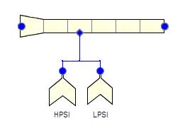
It is not recommended to model the injection or removal line unless there is a specific reason for doing so (e.g., FW line break). FILL components should be connected directly to the injection/removal location. Two systems sharing a common connecting line may be modeled as separate FILLs connected via side junctions to the same cell.
Required Inputs¶
- Flow characteristics (flow rate vs. pressure or time, or controller output)
- Liquid addition/removal location in the plant
- Fluid characteristics (temperature, pressure, boron concentration)
Connection Locations¶
| System | Typical FILL Connection Location |
|---|---|
| FW | FW line inlet or SG downcomer |
| AFW | FW line or SG downcomer (W/CE); SG boiler region (B&W) |
| HPSI | Multiple cold legs |
| LPSI/RHR | Multiple cold legs |
| Charging | One cold leg |
| Letdown | One cold leg |
Component Numbering¶
| System | Component Number |
|---|---|
| Main FW | (Loop) × 100 + 1480 |
| Auxiliary FW | (Loop) × 100 + 1481 |
| HPSI A | (Loop) × 100 + 1080 |
| HPSI B | (Loop) × 100 + 1082 |
| LPSI A | (Loop) × 100 + 1081 |
| LPSI B | (Loop) × 100 + 1083 |
| Charging | (Loop) × 100 + 1084 |
| Letdown | (Loop) × 100 + 1085 |
FILL Component Setup¶
Fill Type (IFTY)¶
| Application | IFTY | Description |
|---|---|---|
| Most systems | 8 | Mass flow with trip |
| FW with control system | 10 | General state CS (flow, pressure, temperature via controller) |
Common Parameters¶
| Parameter | Value |
|---|---|
| IOFF | 2 (state properties held constant when trip off) |
| DXIN | DX of connecting cell |
| VOLIN | VOL of connecting cell |
| ALPIN | 0.0 (all liquid) |
| TLIN | Injection water temperature (system-specific) |
| TVIN | Tsat at input pressure |
| PIN | Injection pressure, or expected steady-state pressure of connecting cell |
| PAIN | 0.0 |
| FLWOFF | 0.0 (flow stops when trip returns to OFF) |
| TWTOLD | 0.0 |
| RFMX | 10²⁰ (no rate restriction) |
| Couple to CONTAN | False (verify for long-term transients with RHR suction from containment) |
| VMSCL | 1.0 |
Initial Mass Flow (FLOWIN)¶
- Systems active during steady state (FW, charging, letdown): Set to steady-state flow rate
- Systems active only during transients (AFW, HPSI, LPSI): Set to 0.0
- Letdown flow values are negative (liquid removal)
Boron Concentration (CONCIN)¶
- HPSI, LPSI/RHR, charging (from RWST): Boron concentration per analysis assumptions
- All other systems: 0.0
- May be set to 0.0 if boron is neglected for conservatism
Fill Tables (VMTBM) — System-Specific¶
HPSI and LPSI/RHR¶
Table of flow rate vs. pressure at injection cell. Include bounding data pairs to ensure zero flow outside the system's operating pressure range:
- First pairs: (0.0, 0.0); (Pmin − 1 kPa, 0.0)
- Middle pairs: Flow curve data
- Last pairs: (Pmax + 1 kPa, 0.0); (10⁹, 0.0)
Signal variable (IBSV) = pressure in connecting cell.
AFW¶
Options:
- Pressure-dependent: Table of flow vs. SG pressure (IBSV = SG pressure signal)
- Pump runup: Table of flow vs. time since trip (negative independent variable form)
- Constant: [(0.0, design flow); (10²⁰, design flow)]
FW, Charging, Letdown¶
Table of flow vs. time since trip (negative independent variable form). Typical patterns:
- Trip-off: [(0.0, FLOWIN); (rampdown time, 0.0)]
- Constant then trip: [(0.0, flow rate); (0.01, 0.0)]
Trip Setup¶
Each system needs an appropriate controlling trip. Example simple trip (charging flow cessation at transient start):
| Parameter | Value |
|---|---|
| Setpoint Range Type | 1 [On(For) || OFF] |
| Initial SET | 0 (On) |
| SETP1 | −1.0 |
| SETP2 | 0.0 |
| ITST | 1 (Signal Variable) |
| IDSG | Problem time signal variable |
More elaborate on/off control systems (e.g., HPSI switchover due to RWST emptying) are covered in the Control Systems guidance.
Changes to Existing Components¶
When FILL components are connected via side junctions, the receiving component needs:
- NSIDES = total number of side connections
- THETA = 90° (or plant-specific angle)
- IENTRN = 1 (offtake model on) for liquid removal from horizontal pipes (letdown)
- IENTRN = 0 for all other situations
Cross-References¶
- Pressurizer — Charging/letdown connections
- Primary Loop — Cold leg injection locations
- Steam Generator (UTSG) / Steam Generator (OTSG) — FW/AFW injection
- Control Systems — FW control system, trip logic
- Containment — CONTAN coupling for long-term RHR
This page faithfully extracts liquid addition and removal system guidance from Rev 1 §16. All systems are modeled as FILL components (IFTY=8 or 10) connected directly to injection/removal locations without intermediate piping. HPSI/LPSI use pressure-dependent flow tables; FW/AFW/charging/letdown use time-dependent tables with trip control.