PWR Steam & Feedwater Circuit Modeling¶
Source
Rev 1 Modeling Guidance, §15 — Steam & Feedwater Circuit Modeling; Appendix A.15 — Steam & Feedwater Circuit Bases.
Overview¶
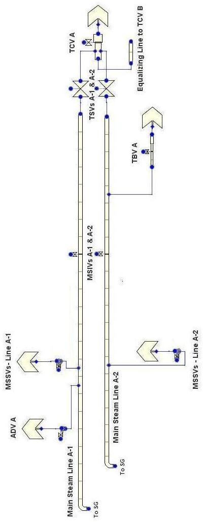
This section provides guidance on modeling the PWR steam circuit from the SG outlet to the turbine/condenser boundary conditions, plus the feedwater line. The guidance is applicable to Westinghouse ⅔/4-loop, CE 2-loop, and B&W PWRs.
The steam circuit is modeled as a collection of VALVE, PIPE, and BREAK components representing the building blocks of a plant-specific steam circuit. Plant configurations vary significantly, so the analyst must adapt this guidance to the specific facility.
Required Inputs¶
- MSL geometry (ID, length), MSIV seat ID/location/loss coefficients/closing time/delay
- MSSV connecting line geometry, rated flow/pressure, seat ID, loss coefficients, opening/closing times/setpoints/delays
- ADV connecting line geometry, rated flow/pressure, seat ID, loss coefficients, opening/closing times
- TSV/TCV seat IDs, locations, loss coefficients, closing times, delays
- TBV line geometry, seat ID, loss coefficients, opening/closing times, rated flow/pressure
- Equalizing line geometry (if applicable)
- FW line geometry, FW ring injection flow area, material properties
- Condenser nominal pressure/temperature, containment initial P/T
- Rated steam flow per MSL, SG nominal pressure
Component Summary¶
| Component | Type | Typical NCELLS | Notes |
|---|---|---|---|
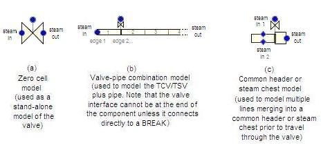
| MSL/MSIV | VALVE | L/(8·ID) + 1, rounded up | DX/HD ≤ 8 for pressure propagation; coarser (≤30) for LOCA |
| MSSV | VALVE | 0 (zero-cell, side-junction) | One per MSSV bank per MSL |
| ADV | VALVE | 0 or 2 | Side-junction connected |
| MSSV/ADV BREAKs | BREAK | — | Containment backpressure (IBTY=0/1/7) |
| TSV/TCV | VALVE | L/(8·ID) + 1 | Often combined; TSV at one edge, TCV at another |
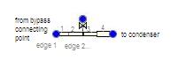
| TBV | VALVE | 0 | Side-junction from MSL or steam chest |
| Equalizing line | PIPE | 2–3 | Connects common headers between loops |
| Turbine BREAK | BREAK | — | Turbine steam chest pressure BC |
| Condenser BREAK | BREAK | — | Condenser pressure BC |
| FW line | PIPE | 3–5 | From FW BC to SG |
Basis — Appendix A.15
"The approach for the steam circuit was to provide guidance in the form of 'building blocks' which could be used to construct facility-specific components from the SG outlets to the turbine control valves. The FW circuit is only modeled as the feedwater line, because the system upstream of the FW isolation point can simply be modeled as a boundary condition."
MSL/MSIV — VALVE¶

- One VALVE component per MSL (one per SG)
- Cell 1 = SG dome outlet to MSL flow restrictor; remaining cells = MSL to steam chest
- MSIV modeled at appropriate edge (IVTY=3, INTLOSSOFF=1)
- NCELLS = 1 + LMSL after restrictor / (8 · IDMSL), rounded up
MSL nodalization: DX/HD ratio of ~8 based on NRC experience with turbine trip transients. For LOCA analyses where secondary phenomena are less important, DX/HD up to ~30 is acceptable.
Basis — Appendix A.15
"The nodalization for the steam circuit is based on recent NRC modeling experience with turbine trip transients, where pressure propagation through the main steam lines is more important. Much of the NRC modeling experience basis is LOCA-specific, where the secondary side attributes beyond the SGs is relatively unimportant."
ADV & MSSV — VALVE¶
- Typically zero-cell VALVE components connected via side junctions to the MSL
- 2-cell option available for ADVs with significant connecting line length
- Each ADV/MSSV connects to a BREAK component representing the containment or atmosphere
MSSV trip: 4-setpoint hysteresis pattern (same as pressurizer SRV):
- Setpoint Range Type: 3 [ON(For) || OFF || On(Rev)]
- SETP1 = closing setpoint, SETP4 = opening setpoint
ADV control: May include a more elaborate control system for controlled cooldown (see §19.5 in Control Systems guidance).
ADV/MSSV BREAK Components¶
Same BREAK setup as PWR containment page guidance — IBTY=0 (constant), IBTY=1 (pressure table), or IBTY=7 (CONTAN coupled). ADVs/MSSVs typically discharge to containment atmosphere.
TSV & TCV — VALVE¶
- TSV and TCV may be combined into one VALVE component or modeled separately
- Models pipe from steam chest/header to turbine
- IVTY=3 for both; TSV trip controlled by turbine trip signal; TCV may use control system
TBV — VALVE (0 cells)¶
- Zero-cell VALVE, side-junction connected to MSL or steam chest
- Models turbine bypass flow to condenser
- IVTY=3; trip and table define TBV opening/closing characteristics
Equalizing Line — PIPE¶
- Connects steam headers between loops to balance pressure
- Simple pipe requiring no special consideration beyond standard modeling
Feedwater Line — PIPE¶

- Models the FW line from the FW regulation boundary condition to the SG
- Last cell includes FW ring volume; last edge FA = FW injection port flow area
- Included primarily for FW line break scenarios and FW line mass inventory
- For non-FW-break transients, the FW line has minimal impact on results
Basis — Appendix A.15
"In typical PWR SGs, the FW travels through the FW line into a FW ring that distributes water evenly into the SG downcomer. In OTSGs, the FW ring is attached to the outside of the SG, so the volume is separate from the SG. Most current models simply neglect the FW ring in the SG downcomer region."
General Notes — All Components¶
- All VALVE components: IVTY=3, INTLOSSOFF=1, KOPEN tables for valve loss
- EPSW = plant-specific or 4.572 × 10⁻⁵ m
- Use Pipewall = per heat structure guidance
Cross-References¶
- Steam Generator (UTSG) / Steam Generator (OTSG) — SG outlet connections
- ECCS — FW and AFW injection
- Control Systems — ADV cooldown control, TCV/TBV logic
- Containment — ADV/MSSV BREAK boundary conditions
This page faithfully extracts steam and feedwater circuit guidance from Rev 1 §15. The steam circuit is modeled as building blocks (VALVE, PIPE, BREAK) that the analyst assembles per plant-specific configuration. MSL nodalization uses DX/HD≤8 for pressure propagation accuracy. All valves use IVTY=3 with INTLOSSOFF=1.