BWR Channel Modeling
Source
TRACE V5.0 USER’S MANUAL Volume 2: Modeling Guidelines;
Overview
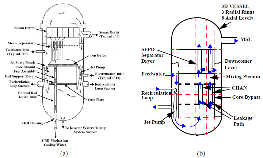
The CHAN component is used to simulate one or more BWR fuel assemblies within the core region of a BWR pressure vessel. Figure 2-23a shows a simplified reactor vessel cutaway, illustrating the key components within a BWR reactor vessel, including the fuel assemblies. Figure 2-23b shows these same key components within a BWR reactor vessel, but in the context of a nodalization diagram of an actual TRACE BWR model.
A BWR fuel assembly consists of a fuel bundle (a square array of fuel and water rods with support hardware) enclosed by a channel that directs core flow and guides control rods. The versatile CHAN component can simulate any past or present BWR assembly design. The number of CHAN components required in a model depends on 3D vessel noding, radial power distribution, assembly types, and inlet orifice configuration.
The CHAN component consolidates all input for a BWR model, internally spawning the necessary TRACE 1D hydraulic, heat structure, and radiation sub-components to simulate flow and heat transfer. The CHAN component automatically generates the following sub-components based on user input (NCHANS):
-
PIPE Components: Model in-channel flow, water rod flow, and leakage paths (e.g., inlet nozzle to bypass, finger springs).
-
HTSTR Components: Simulate fuel rod conduction, gap and convective heat transfer, water rod heat transfer, and two-sided canister wall conduction between internal fluid and the core bypass.
-
RADENC Components: Account for radiation heat transfer to cooler channel walls during dryout.
With upward flow moving from the lower to the mixing plenum, distinct 1D hydro and HTSTR components are assigned to each fuel rod group, water rod, and the canister wall.
Interfaces With Other Components
Before exploring CHAN modeling features, its two key external interfaces must be understood:
- VESSEL Component: The 3D structure where the CHAN component is typically housed.
- POWER Component: The TRACE component that supplies power to the CHAN's HTSTR sub-components.
Interfaces with the VESSEL Component
BWR fuel assemblies are typically modeled inside a host component—most commonly a 3D VESSEL, but optionally a PIPE or TEE—controlled by the IPVHT variable.
- IPVHT > 0 (Dynamic Coupling): Couples the outer canister wall directly to the host component’s hydraulic cells for core bypass heat transfer. Requires IDROD (horizontal cell) and NHCELO (axial levels) arrays; ignores HOUTL, HOUTV, TOUTL, and TOUTV.
-
IPVHT = 0 (Simplified/Adiabatic Wall): Bypasses fluid coupling. Uses constant boundary values (HOUTL, HOUTV, TOUTL, TOUTV) or makes the wall adiabatic (if set to zero), which is ideal for fast transients. IDROD and NHCELO are omitted.
-
JUN1 & JUN2: Inlet and outlet junctions must be listed in the host VESSEL's LJUNS array.
- JUNLK: The leakage path points directly to the core bypass cell and does not require VESSEL source entries.
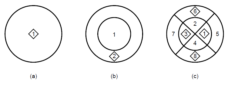
| IDROD | NHCELO | |
|---|---|---|
| One horizontal cell - One CHAN | idrod 1 e | nhcelo 2 3 4 e |
| Two horizontal cells - One CHAN in each cell | idrod 2 e | nhcelo 2 3 4 s |
| Eight horizontal cells - One CHAN in four of the eight cells: 1, 3, 5, 7 | idrod 1 3 6 8 e | nhcelo 2 3 4 s nhcelo 2 3 4 s nhcelo 2 3 4 s nhcelo 2 3 4 e |
Recommendation
Ensure high-energy break flow is added directly to the CONTAN component rather than through a PIPE-to-CONTAN BREAK connection. Review all BREAK connections between PIPE and CONTAN components for consistency.
Cross-References
- Break Modeling — BREAK components coupled to CONTAN (IBTY=7)
- Steam Lines — SRV/ADS discharge to suppression pool
- PWR Containment — PWR BREAK BC approach (no PWR-specific CONTAN guidance yet)
This page faithfully extracts BWR containment modeling guidance from the BWR Containment Guidance (8-31-16). The CONTAN component family includes COMPARTMENT (drywell and wetwell), Passive Junctions (vents and vacuum breakers), and fan coolers. Mark I, II, and III containment designs are covered. The explicit numerical solver is recommended over semi-implicit due to CPU time considerations.