Once-Through Steam Generator (OTSG) Modeling¶
Source
Rev 1 Modeling Guidance, §7 — SG Primary Side (OTSGs); §14 — SG Secondary Side (OTSGs); Appendix A.7 — SG Primary Side Bases (OTSGs); Appendix A.14 — SG Secondary Side Bases (OTSGs).
Overview¶
This section provides guidance on modeling the primary and secondary sides of once-through steam generators (OTSGs) in TRACE. The guidance is applicable to:
- Babcock & Wilcox (B&W) PWRs
This guidance is not applicable to U-tube steam generators used in Westinghouse or Combustion Engineering plants — see the UTSG Modeling page — or to helical coil SGs proposed for some SMRs.
Key differences from UTSG modeling:
- Straight tubes (no U-bend) — primary flow enters at top, exits at bottom
- No steam separator — OTSGs produce superheated steam directly
- Upper/lower tubesheet — tubes span the full SG height
- Upper and lower downcomer — separated by a divider, with aspiration flow path
- Finer nodalization at top — needed to resolve steam superheating above dryout point
- Three SJC flow paths — liquid (lower DC → boiler), aspiration (boiler → lower DC), and steam (boiler → upper DC)
Required Inputs¶
Primary Side¶
- Reactor vessel outlet and inlet fluid temperatures
- Primary loop nominal system pressure
- SG inlet and outlet plena geometry (ID, height, total volume, wall thickness)
- SG plenum material properties (thermal conductivity, heat capacity, wall roughness)
- SG tube geometry (ID, total length)
- SG upper and lower tubesheet geometry (thicknesses)
- SG tube material properties (roughness)
- Number of SG tubes
- % Steam generator tube plugging (SGTP)
- Loss coefficients for fittings, nozzles, etc.
Secondary Side¶
- Nominal SG steam dome pressure
- Nominal feedwater and steam outlet flow
- Nominal aspirator steam flow
- Main steam line diameter
- SG secondary side geometry (boiler region ID, shell OD, shroud dimensions)
- SG tube geometry (OD, pitch)
- SG tube external wall roughness
- Loss coefficients for tube support plates
- Flow path geometry for: liquid flow (lower DC → boiler), steam flow (boiler → upper DC), aspiration flow (boiler → lower DC)
Primary Side¶
The OTSG primary side is modeled as three PIPE components: inlet plenum, SG tubes, and outlet plenum.
SG Inlet Plenum — PIPE (1 cell, 2 edges)¶
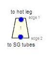
Component setup:
- Total Length = SG inlet plenum height
- NCELLS = 1, NPIPES = 1
- Orientation = Vertical
- Component Number = (Loop Number) × 100 + 1005
Geometry¶
| Parameter | Value |
|---|---|
| DXcell1 | SG inlet plenum height |
| VOLcell1 | Half spheroid = 2π/3 · (IDplenum/2)² · DX₁ |
| FAedge1 | π/4 · ID²inlet nozzle |
| FAedge2 | Ntubes · π/4 · ID²single tube (adjusted for SGTP) |
| HDedge1 | IDinlet nozzle |
| HDedge2 | IDone SG tube |
Plenum Geometry
The OTSG inlet plenum is modeled as half a spheroid, unlike the UTSG which uses a half spherical cap. If the inner diameter is not explicitly known, it may be assumed equal to the SG shell ID.
Friction¶
| Edge | NFF | KFAC | KFACR |
|---|---|---|---|
| 1 | 0 | 16 fT (standard elbow, 45°) | 16 fT |
| 2 | 0 | 0.5 · (1 − β²) contraction | (1 − β²)² expansion |
- β = IDone tube / HDinlet plenum (where HDplenum = (4 · FAplenum / π)0.5)
- ICFLG = 0 at all edges; CCFL not applied at plenum edges
Initial Conditions & General Inputs¶
Same approach as UTSG inlet plenum:
- P = nominal primary pressure; TL, TV = RV outlet temperature
- ALPN = 0.0; PA = 0.0
- EPSW = plant-specific or 4.572 × 10⁻⁵ m (commercial steel)
- IPOW = 0, IACC = 0, NSIDES = 0
- Use Pipewall = False
OTSG Tubes — PIPE (11 cells, 12 edges)¶

Component setup:
- Total Length = tube length + upper tubesheet thickness + lower tubesheet thickness
- NCELLS = 11
- NPIPES = total tubes (or adjusted for SGTP: [1 − SGTP%/100] × total)
- HD = IDone SG tube
- Component Number = (Loop Number) × 100 + 1010
Cell Layout¶
| Cells | DX | Description |
|---|---|---|
| 1 | Upper tubesheet thickness | Upper tubesheet |
| 2–3 | Tube length (upper section) / 2 | Upper tube section (finer — see basis) |
| 4–10 | Tube length (remaining) / 7 | Main tube section |
| 11 | Lower tubesheet thickness | Lower tubesheet |
Basis — Appendix A.7
"The nodalization was developed based on modeling experience with LOCA analyses to adequately capture the key thermal hydraulic phenomena as documented in the applicable PIRTs without unnecessary increases in computational time, with the exception of non-uniform wetting of the SG tubes."
"All of the tubes are lumped into a single PIPE component with the NPIPES input used to set the number of parallel identical components. Non-uniform wetting phenomena in OTSGs, where certain tubes experience different conditions than others, have been shown to be applicable to OTSG-specific thermal hydraulic phenomena. Scaled versions of the OTSGs used in the MIST facility have a relatively long spray region in which liquid from the EFW header is not distributed to all SG tubes. Therefore, in an OTSG, a large number of tubes will not be directly sprayed."
Edge Geometry¶
- FAall edges = π/4 · ID²one tube
- HDall edges = IDone tube
- VOLcells = FA × DX (cylindrical tubes)
- All edges vertical: GRAV = −1.0 (primary flow descends from inlet plenum at top to outlet plenum at bottom)
CCFL¶
CCFL is not applied at any OTSG tube edges in the standard nodalization. (Unlike UTSGs, there is no U-bend or tubesheet flooding concern in the standard configuration.)
Friction¶
| Edge | NFF | KFAC | KFACR |
|---|---|---|---|
| 1 | 0 | 0.5 · (1 − β²) contraction | (1 − β²)² expansion |
| 2–11 | 1 | 0.0 | 0.0 |
| 12 | 0 | (1 − β²)² expansion | 0.5 · (1 − β²) contraction |
- Edge 1: β = IDtube / HDinlet plenum
- Edge 12: β = IDtube / HDoutlet plenum
- ICFLG = 0 at all edges
General Inputs¶
- EPSW = plant-specific or 1.524 × 10⁻⁶ m (drawn piping)
- NSIDES = 0, IACC = 0, IPOW = 0
- Use Pipewall = False (HTSTR components attached manually)
SG Outlet Plenum — PIPE (1 cell, 2 edges)¶
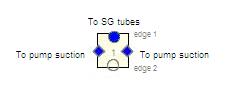
Component setup:
- Total Length = SG outlet plenum height
- NCELLS = 1, NPIPES = 1
- Component Number = (Loop Number) × 100 + 1015
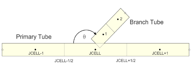
B&W plants have two cold legs per loop. Both intermediate legs are connected via side junctions:
- NSIDES = 2
- Side junction angle = plant-specific or 135° (consistent with UTSG outlet plenum guidance)
- FAedge2 = 0.0 (flow exits via side junctions)
- HDedge2 = 1.0 × 10¹⁰ (TRACE requires HD > 0)
Basis — Appendix A.7
"B&W plants have two cold legs per loop. Therefore, both intermediate legs are connected via side junctions with an appropriate angle (consistent with the orientation of the SG outlet nozzles). This will ensure that both legs are treated equally by the code and analyst."
Primary Side Summary¶
Secondary Side¶
The OTSG secondary side is modeled as two PIPE components (boiler region and downcomer) and three SJC components (lower liquid flow, aspiration flow, and upper steam flow).
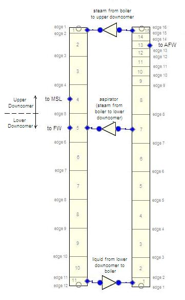
SG Boiler Region — PIPE (15 cells, 16 edges)¶
Component Number = (Loop Number) × 100 + 1410
Cell Layout¶
The boiler region is nodalized consistently with the primary side tube component. The upper portion is finely nodalized to resolve steam superheating above the dryout point.
| Cells | DX | Description |
|---|---|---|
| 1 | Hlower DC-to-boiler flow path | Bottom (flow path height) |
| 2 | DXcell10,OTSG tube − Hflow path | Coupled to tube cell 10 |
| 3–8 | DXcells9-4,OTSG tube | Coupled to tube cells (1:1) |
| 9–11 | ⅓ · DXcell3,OTSG tube | Fine mesh — superheating region |
| 12–14 | ⅓ · (DXcell3,OTSG tube − Hboiler-to-upper DC) | Fine mesh continuation |
| 15 | Hboiler-to-upper DC flow path | Top (upper flow path height) |
Basis — Appendix A.14
"Modeling experience and studies indicated the need for finer nodalization in the upper part of the boiler region to obtain finer resolution of the change in temperature above the point at which dryout occurs, when the vapor becomes superheated by the primary side fluid. The fluid temperature does not change as quickly on the primary side due to the much higher heat capacity of liquid, but the vapor temperature changes quickly and is a very important parameter in indicating proper OTSG performance."
Volume — Account for Tube Displacement¶
Note: Unlike UTSGs, the factor of 2 on Ntubes is not needed because OTSG tubes are straight (each tube displaces volume only once per axial level).
Edge Geometry¶
| Edge | FA | HD |
|---|---|---|
| 1 | 0.0 (SJC provides flow path) | 0.0 |
| 2–15 | π/4 · ID²boiler − Ntubes · π/4 · OD²tube | 4 · FAunit cell / (π · ODtube) |
| 16 | 0.0 (SJC provides flow path) | 0.0 |
Basis — Appendix A.14
"The hydraulic diameter is calculated based on a unit cell of the SG tube lattice. The region between the SG tubes and the SG shroud is not significant enough to affect the hydraulic calculation, so the unit-cell hydraulic diameter is simply used for convenience."
Friction¶
- NFFedges1,16 = 0; NFFedges2-15 = 1
- KFACedges2-15 = ktube support plates (if known)
- ICFLG = 0 at all edges
- No CCFL applied
Basis — Appendix A.14
"Some consideration was given to the possibility that a CCFL model was necessary due to AFW injection in the upper part of the boiler region. Currently available information does not seem to suggest that one is necessary, so the current guidance was developed without one."
Initial Conditions¶
- P = nominal SG pressure
- TL = saturation temperature at SG pressure (subcooled cells) or feedwater temperature
- TV = saturation temperature (lower cells) or superheated temperature (upper cells where dryout has occurred)
- ALPN = plant-specific or estimated based on boiling characteristics
- VL, VV = estimated from nominal flows, or 0.0
General Inputs¶
- NSIDES = 3 (for three SJC connections); THETA = 90° for all
- IENTRN = 0 (offtake model off for all)
- IACC = 0, IPOW = 0
- Use Pipewall = False
SG Downcomer — PIPE (11 cells, 12 edges)¶
Component Number = (Loop Number) × 100 + 1400
The downcomer is a single PIPE component representing both the upper and lower downcomer regions. The flow area at the divider elevation is set to zero, effectively separating the upper and lower regions while keeping them in one component for numbering convenience.
Basis — Appendix A.14
"The downcomer in OTSGs is a simple annular cylinder. It is subdivided into an upper and lower downcomer. Many models use separate PIPE components, but a single component was assumed in the modeling guidance for convenience in component numbering standardization. The two approaches are fundamentally identical. The flow area at the elevation where the downcomer divider is located is set to zero."
Nodalization Constraints¶
The downcomer nodalization is driven by:
- Heights of the upper and lower flow paths between downcomer and boiler region
- Location of the divider between upper and lower downcomer
- Consistency with boiler region for heat structure coupling via the shroud
The upper and lower cells are sized to preserve flow path heights. The remaining cells are uniformly distributed within each downcomer region.
Volume and Flow Area¶
- VOL = π/4 · (OD²downcomer − ID²downcomer) · DX — annular geometry
- FA at divider edge = 0.0 (no flow across divider)
- FA at other edges = π/4 · (OD²downcomer − ID²downcomer)
Connections¶
- Feedwater injects at the cell at the appropriate elevation
- Main steam line connects at the cell at the appropriate elevation
- Auxiliary feedwater connects at the appropriate elevation
- The analyst should renodalize if feedwater and main steam line would connect to the same cell
Three SJC Flow Paths¶
Three SJC components model the flow paths between downcomer and boiler region:
| SJC | Flow Path | Component Number |
|---|---|---|
| Lower Liquid | Lower downcomer → boiler region bottom | (Loop) × 100 + 1405 |
| Aspiration | Boiler region → lower downcomer (steam heating of incoming liquid) | (Loop) × 100 + 1415 |
| Upper Steam | Boiler region top → upper downcomer | (Loop) × 100 + 1420 |
All SJC junctions: angle = 90°, IENTRN = 0 (offtake model off).
Basis — Appendix A.14
"Three flow paths exist between the downcomer and the boiler region of OTSGs: the lower liquid flow from the lower downcomer to the boiler region, the upper superheated flow from the boiler region to the upper downcomer, and an aspirator flow path at the upper part of the lower downcomer. The aspirator allows fluid from the boiler region to flow into the lower downcomer, where it condenses and heats the incoming liquid, while the other two flow paths act as inlet/outlet flow paths for the boiler region."
"No offtake models are activated for the side junctions. The only flow path for which the offtake model might be significant is the aspirator flow path, and no well-defined water level is expected across the span of the boiler region."
Steady-State Checklist¶
Steady-State Verification
- Primary-side ΔP across SG matches plant data
- Secondary-side pressure equals nominal SG steam dome pressure
- SG thermal power matches target
- Steam outlet temperature shows appropriate superheat
- Reactor vessel outlet and inlet temperatures match plant data
- Dryout point elevation is physically reasonable
- Aspiration flow rate is consistent with plant design
- Downcomer divider effectively separates upper/lower regions (FA = 0)
- 10:1 adjacent cell volume ratio is satisfied throughout
- NPIPES reflects current SG tube plugging level
Cross-References¶
- UTSG Modeling — U-tube SG guidance for Westinghouse/CE plants
- Primary Loop — Hot leg (with candy-cane bend for B&W), intermediate leg, RCP
- Pressurizer — Pressure control
- Heat Structures — SG tube and shroud HTSTR guidance (§17)
This page faithfully extracts OTSG modeling guidance from Rev 1 §7 (primary side) and §14 (secondary side), with associated bases from Appendix A.7 and A.14. B&W plants may have raised or lowered loop configurations; this guidance assumes a lowered loop (most common). For raised-loop configurations, the basic nodalization is expected to be applicable with the straight-pipe segment relocated from the intermediate leg to the hot leg.