BWR Recirculation Pump Modeling
Source
BWR Modeling Guidance — Recirculation Pump Modeling.
Overview
This section provides guidance on modeling BWR recirculation pumps in TRACE. The pump and discharge nozzle are modeled as a PUMP component (IPMPTY=2); the pump suction nozzle is modeled as a separate PIPE component. The guidance is applicable to:
- GE BWR/3, BWR/4, BWR/5, and BWR/6
Typical BWR plants have two recirculation loops, so two PUMP components and two suction nozzle PIPE components should be created.
Required Inputs
- Nominal system pressure and core inlet subcooling
- Change in pressure across the recirculation pump
- Pump suction and discharge nozzle geometry (ID, length)
- Pump water volume
- Height from pump suction to pump discharge mid-plane
- Pump moment of inertia
- Pump rated head, torque, volumetric flow, density, and impeller speed
- Single-phase and degraded homologous pump curves (head and torque)
- Loop mass flow rate
Pump Suction Nozzle — PIPE (1 cell, 2 edges)
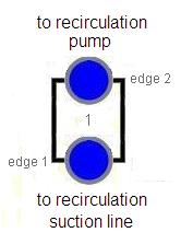
Component Number = (Loop) × 100 + 1025 (pump A) or + 1055 (pump B)
Geometry
| Parameter | Value |
|---|---|
| DXcell1 | Pump suction nozzle length |
| VOLcell1 | Frustum: π·DX/12·(ID²suction line + ID²pump suction + IDsuction · IDpump) |
| FAedge1 | π/4 · ID²suction line |
| FAedge2 | π/4 · ID²pump suction |
| HDedge1 | IDsuction line |
| HDedge2 | IDpump suction |
| GRAV | +1.0 (vertical upward) |
Friction
- NFFedge1 = 1; NFFedge2 = 0
- KFAC = 0.0 at all edges — all losses included in manufacturer pump head curves
- KFACR = 0.0; ICFLG = 0; CCFL not applied
General Inputs
- ICONC = 0; IPOW = 0; EPSW = plant-specific or 4.572 × 10⁻⁵ m
- NSIDES = 0; IACC = 0
Recirculation Pump — PUMP (2 cells, 3 edges)
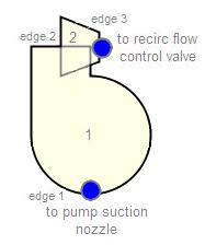
Component Number = (Loop) × 100 + 1030 (pump A) or + 1060 (pump B)
Initialization:
- IPMPTY = 2 (equation-based rotational speed)
- NCELLS = 2
- Total Length = height from suction nozzle to discharge mid-plane + discharge nozzle length
Cell Layout
| Cell | DX | VOL |
|---|---|---|
| 1 (pump body) | 2 × height from suction outlet to discharge mid-plane | Pump water volume (from manufacturer) |
| 2 (discharge nozzle) | Discharge nozzle length | Frustum: π·DX/12·(ID²discharge line + ID²pump discharge + IDline · IDpump) |
Cell 1 DX
Half of cell 1 DX must equal the elevation change from pump suction outlet to discharge mid-plane. TRACE assumes zero elevation change across edge 2 in the momentum equation. Otherwise, the net gravitational head calculated for the loop will be incorrect.
Edge Geometry
| Edge | FA | HD | GRAV |
|---|---|---|---|
| 1 (suction) | π/4 · ID²pump suction | IDpump suction | +1.0 (vertical) |
| 2 (pump-to-discharge) | π/4 · ID²pump discharge | IDpump discharge | 0.0 (horizontal) |
| 3 (discharge outlet) | π/4 · ID²discharge line | IDdischarge line | 0.0 (horizontal) |
- CCFL: not applied; ICFLG = 0 at all edges (impeller choking is in the pump curves)
Friction
- NFFedges1,2 = 0; NFFedge3 = 1
- KFAC = 0.0 at all edges — all losses included in manufacturer pump curves
- KFACR = 0.0
Initial Conditions
- P = plant-specific suction/discharge pressure, or nominal system pressure
- TL = plant-specific or Tsat − ΔTsubcooling; TV = Tsat
- ALPN = 0.0; PA = 0.0
- VL = ṁloop / (ρ · FAedge); VV = 0.0
Pump Performance Data
All pump performance parameters must be obtained for the specific pump being modeled. No generic recommendations are provided.
Rated Values
| Parameter | Description |
|---|---|
| RHEAD | Rated head |
| RTORK | Rated torque |
| RFLOW | Rated volumetric flow |
| RRHO | Rated density |
| ROMEGA | Rated impeller speed |
Frictional Torque Coefficients
| Parameter | Description |
|---|---|
| TFR0–TFR3 | Frictional torque polynomial coefficients |
| TFRB | Torque break speed |
| TFRL0–TFRL3 | Low-speed frictional torque coefficients |
Speed Values
| Parameter | Value |
|---|---|
| OMEGAN (initial speed) | Nominal rotational speed (BWR/5-6 constant speed); 0.0 otherwise |
| OMGOFF (off speed) | 0.0 (typical transients don't re-activate pumps) |
| ROMGMX (max speed change) | 10²⁰ (no restriction) |
| OMGSCL (speed scale factor) | 1.0 |
| NPMPSD (off-speed controller) | Control block output for variable speed (BWR/3-4); 0 for constant speed |
Homologous Pump Curves
| Curve | Description |
|---|---|
| HSP | Single-phase homologous head curve |
| HTP | Fully degraded homologous head curve |
| TSP | Single-phase homologous torque curve |
| TTP | Fully degraded homologous torque curve |
| HDM | Head degradation multiplier curve |
| TDM | Torque degradation multiplier curve |
Pump Curve Option (OPTION)
- OPTION = 0 — User-specified curves (preferred if plant-specific data available)
- OPTION = 4 — Built-in Westinghouse curves (fallback if no plant-specific data)
Other General Inputs
| Parameter | Value |
|---|---|
| IRP (reverse rotation) | Plant-dependent: 0 (No) or 1 (Yes) |
| IPM (degradation option) | 1 (single/two-phase curves) if OPTION ≠ 3,4; 2 (two-phase multipliers) if OPTION = 3,4 |
| EFFMI | Manufacturer-specified effective moment of inertia |
| ETA | Pump efficiency (default 85% if not provided) |
| Use Alternate Inertia | False (not recommended for typical BWR modeling) |
| IPMPTR | Trip ID controlling pump speed |
| IPOW | 0 (use PUMPFRICQ namelist for frictional heat) |
| Use Pipewall | False (attach HTSTR to cells 1–2 manually) |
Steady-State Checklist
Steady-State Verification
- Pump ΔP matches plant data
- Loop flow rate matches target
- Pump speed is at rated value (constant speed) or target value (variable speed)
- Pump efficiency is consistent with rated parameters
- 10:1 adjacent cell volume ratio satisfied (check against adjacent recirc line cells)
Cross-References
- Recirculation Lines — Suction and discharge piping
- Jet Pump — Driven by recirculation pump output
- Reactor Vessel — RPV connections
This page faithfully extracts recirculation pump modeling guidance from the BWR Modeling Guidance. The pump is modeled as a 2-cell PUMP component (IPMPTY=2) with separate suction nozzle PIPE. All hydraulic losses are assumed included in the manufacturer pump curves — no KFAC values are applied. BWR/3-4 use variable speed control (NPMPSD); BWR/5-6 use constant speed (OMEGAN).