U-Tube Steam Generator (UTSG) Modeling¶
Source
Rev 1 Modeling Guidance, §4 — SG Primary Side (U-Tube SGs); §13 — SG Secondary Side (U-Tube SGs); Appendix A.4 — SG Primary Side Bases; Appendix A.13 — SG Secondary Side Bases.
Overview¶
This section provides guidance on modeling the primary and secondary sides of U-tube steam generators (UTSGs) in TRACE. The guidance is applicable to:
- Westinghouse 2-loop, 3-loop, and 4-loop PWRs
- Combustion Engineering 2-loop PWRs
This guidance is not applicable to once-through steam generators (OTSGs) used in Babcock & Wilcox plants — see the OTSG Modeling page — or to helical coil SGs proposed for some SMRs.
Required Inputs¶
Primary Side¶
- Reactor vessel outlet and inlet fluid temperatures
- Primary loop nominal system pressure
- SG primary side pressure drop
- SG inlet and outlet plena geometry (ID, height, total volume)
- SG plenum material properties
- SG U-tube geometry (ID, length, average bend radius)
- SG U-tube material properties
- Number of SG U-tubes
- % Steam generator tube plugging (SGTP)
- Loss coefficients for fittings, nozzles, etc.
- SG plenum and U-tube wall roughness
Secondary Side¶
- Nominal SG steam dome pressure
- Nominal feedwater and steam outlet flow
- Main steam line diameter
- SG secondary side geometry (boiler region ID, shell OD, shroud dimensions)
- SG U-tube geometry (OD, pitch)
- Primary separator geometry (riser cylinder dimensions, swirl vane inlet location, outer drainage cylinder dimensions, total height)
- Secondary separator geometry (height, total volume, inlet/outlet flow areas)
- SG separator carryover and carryunder
- Nominal SG separator inlet quality
- Loss coefficients for tube support plates and SG separators
- Flow path geometry for downcomer-to-boiler region connection
Primary Side¶
The SG primary side is modeled as three PIPE components: inlet plenum, U-tubes, and outlet plenum.
SG Inlet Plenum — PIPE (1 cell, 2 edges)¶
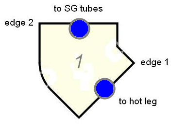
Component setup:
- Total Length = SG plenum height
- NCELLS = 1
- NPIPES = 1
- Orientation = Vertical
- Component Number = (Loop Number) × 100 + 1005
Geometry¶
| Parameter | Value |
|---|---|
| DXcell1 | SG plenum height |
| VOLcell1 | ½ volume of cap = π · DX₁² · (3 · IRplenum − DX₁) / 6 |
| FAedge1 | π · ID²inlet nozzle / 4 |
| FAedge2 | NPIPES × π · ID²U-tube / 4 (set by U-tube component) |
| HDedge1 | IDinlet nozzle |
| HDedge2 | IDone U-tube |
| CCFL | None at either edge |
| GRAVedge1 | sin(45°) = 0.707 if angle unknown |
| GRAVedge2 | 1.0 (vertical) |
Plenum Volume
If measured SG primary volumes are available from the NSSS vendor, use those values. Otherwise, calculate using the half-spherical-cap formula above. The plenum hydraulic diameter is HD = (4 · FA / π)0.5. If the inner diameter is not explicitly known, it may be assumed equal to the ID of the SG boiler region.
Friction¶
| Edge | NFF | KFAC | KFACR | ICFLG |
|---|---|---|---|---|
| 1 | 0 | 16 fT (standard elbow, 45°) | 16 fT | 0 |
| 2 | 0 | 0.5 · (1 − β²) sudden contraction | (1 − β²)² sudden expansion | 0 |
- β = IDone U-tube / HDinlet plenum
- fT = Darcy friction factor for smooth commercial steel pipe (Table 1.5-1)
Initial Conditions¶
- P = plant-specific or nominal primary system pressure
- TL = plant-specific or reactor vessel outlet temperature
- TV = reactor vessel outlet temperature
- ALPN = 0.0 (all liquid)
- PA = 0.0 (no non-condensables)
- VL, VV = plant-specific or 0.0
General Inputs¶
- ICONC: per §1.6; CONC = nominal boron concentration (ppm)
- IPOW = 0 (no fluid power)
- EPSW = plant-specific or 4.572 × 10⁻⁵ m (commercial steel)
- NSIDES = 0, IACC = 0, JUNLK ≠ 0
- Use Pipewall = False (use manually attached HTSTR components)
SG U-Tubes — PIPE (19 cells, 20 edges)¶
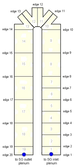
Component setup:
- Total Length = average U-tube length + 2 × tubesheet thickness
- NCELLS = 19
- NPIPES = total U-tubes (or adjusted for SGTP: [1 − SGTP%/100] × total)
- HD = IDone SG tube
- Component Number = (Loop Number) × 100 + 1010
Tube Plugging
NPIPES accounts for SG tube plugging. If NPIPES is changed, the flow area for the upper edges of the SG plena must also be updated. SNAP will adjust automatically if changes are made through the GUI.
Cell Layout¶
| Cells | DX | Description |
|---|---|---|
| 1, 19 | Tubesheet thickness | Tubesheet flow path |
| 2–7 | Lstraight / 10 | Hot-side straight tubes (finer mesh) |
| 8–9 | Lstraight / 5 | Hot-side upper straight section |
| 10–13 | 2π · IRavg U-bend / 8 | U-bend region (¼ circle each) |
| 14–18 | Lstraight / 5 | Cold-side straight tubes |
Basis — Appendix A.4
"The part of the U-tube nearest to the inlet plenum (and thus carrying hotter fluid) is more finely nodalized than the remaining U-tube section. This helps capture the steeper temperature gradients due to higher heat transfer in this region."
Edge Geometry¶
- FAall edges = π · ID²one U-tube / 4
- HDall edges = IDone U-tube
- VOLcells = FA × DX (cylindrical tubes)
CCFL at Tubesheet Inlet (Edge 2)¶
CCFL is applied at the SG tubesheet inlet interface (edge 2 only) for reflux-condensation scenarios during SBLOCAs:
| Parameter | Value |
|---|---|
| CBETA | 0.0 (Wallis correlation) |
| CCFLM | 1.0 |
| CCFLC | 0.8 |
Basis — Appendix A.4
"A CCFL model is necessary at the tubesheet inlet interface, since during SBLOCAs, reflux-condensation transients may occur, leading to countercurrent flow in the hot leg. The CCFL model is based on recommended values from available publications bolstered by assessments based on tests at the Bethsy, ROSA-IV, and LOFT test facilities."
Orientation¶
| Edges | Angle | GRAV |
|---|---|---|
| 1–10 (ascending hot side) | +π/2 | +1.0 |
| 11 (entering U-bend) | +π/4 (or known) | +0.707 |
| 12 (U-bend apex) | 0.0 | 0.0 |
| 13 (leaving U-bend) | −π/4 (or known) | −0.707 |
| 14–20 (descending cold side) | −π/2 | −1.0 |
Basis — Appendix A.4
"The U-bend is simply approximated by the use of four nodes with 45-degree changes in direction for each successive edge. Therefore, the exact average elevation for the SG U-tubes is not perfectly modeled. It is the current position of NRC staff that this modeling is adequate to account for most, if not all analysis scenarios of interest."
Friction¶
| Edge | NFF | KFAC | KFACR |
|---|---|---|---|
| 1 | 0 | 0.5 · (1 − β²) contraction | (1 − β²)² expansion |
| 2–11, 13–19 | 1 | 0.0 | 0.0 |
| 12 (U-bend) | 1 | 50 fT (close-pattern return bend) | 50 fT |
| 20 | 0 | (1 − β²)² expansion | 0.5 · (1 − β²) contraction |
- Edge 1: β = HDedge1 / HDinlet plenum
- Edge 12: fT from Table 1.5-1 (this is a rough estimate; verify via primary-side ΔP)
- Edge 20: β = IDone U-tube / HDoutlet plenum
- ICFLG = 0 at all edges
General Inputs¶
- EPSW = plant-specific or 1.524 × 10⁻⁶ m (drawn piping — note: different from plenum roughness)
- NSIDES = 0, IACC = 0, IPOW = 0
- Use Pipewall = False (HTSTR components attached manually for SG tube heat transfer)
SG Outlet Plenum — PIPE (1 cell, 2 edges)¶
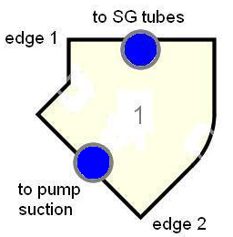
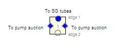
Component setup:
- Total Length = SG plenum height
- NCELLS = 1, NPIPES = 1
- Component Number = (Loop Number) × 100 + 1015
Geometry¶
| Parameter | Single IL | Two ILs |
|---|---|---|
| FAedge1 | NPIPES × π · ID²U-tube / 4 | Same |
| FAedge2 | π · ID²outlet nozzle / 4 | 0.0 (use side junctions) |
| HDedge2 | IDoutlet nozzle | 1.0 × 10¹⁰ (TRACE requires HD > 0) |
| NSIDES | 0 | 2 (side junctions at 135°) |
Basis — Appendix A.4
"For two-cold-leg loops, the recommendation is to connect both intermediate legs via side junctions with an appropriate angle (consistent with the orientation of the SG outlet nozzles). This will ensure that both legs are treated equally by the code and analyst."
Friction¶
| Edge | NFF | KFAC | KFACR |
|---|---|---|---|
| 1 | 0 | (1 − β²)² expansion | 0.5 · (1 − β²) contraction |
| 2 (single IL) | 0 | 16 fT (standard elbow) | 16 fT |
| 2 (two ILs) | 0 | 0.0 | 0.0 |
Primary Side Geometry Summary¶
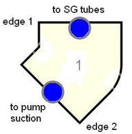
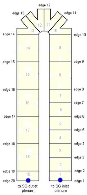
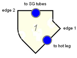
Table 4.6-1: Primary Side Geometry Input Summary (click to expand)
| Region | Node | DX | Edge | FA | HD | CCFL | GRAV | KFAC | KFACR | NFF |
|---|---|---|---|---|---|---|---|---|---|---|
| Inlet plenum → | — | — | 1 inlet | π·ID²nozzle/4 | IDnozzle | None | sin(45°) | 16fT | 16fT | 0 |
| Inlet plenum | 1 | Plenum height | — | VOL/DX | (4·FA/π)0.5 | — | — | — | — | — |
| Plenum → tube | — | — | 2 inlet | NPIPES·π·ID²tube/4 | IDtube | None | 1.0 | 0.5(1−β²) | (1−β²)² | 0 |
| Tubesheet | 1 | Thickness | 1 tube | π·ID²tube/4 | IDtube | None | 1.0 | — | — | — |
| 2 tube | Same | Same | CCFL | 1.0 | 0.0 | 0.0 | 1 | |||
| Hot side | 2–7 | Lstr/10 | 3–10 | Same | Same | None | 1.0 | 0.0 | 0.0 | 1 |
| Hot side upper | 8–9 | Lstr/5 | 11 | Same | Same | None | sin(45°) | 0.0 | 0.0 | 1 |
| U-bend | 10–13 | 2π·Ravg/8 | 12 | Same | Same | None | 0.0 | 50fT | 50fT | 1 |
| Cold side upper | 14–18 | Lstr/5 | 13 | Same | Same | None | sin(−45°) | 0.0 | 0.0 | 1 |
| Tubesheet | 19 | Thickness | 14–19 | Same | Same | None | −1.0 | 0.0 | 0.0 | 1 |
| Tube → plenum | — | — | 20 | Same | Same | None | −1.0 | (1−β²)² | 0.5(1−β²) | 0 |
| Outlet plenum | 1 | Plenum height | — | VOL/DX | (4·FA/π)0.5 | — | — | — | — | — |
| Outlet plenum → | — | — | 2 outlet | π·ID²nozzle/4 | IDnozzle | None | sin(−45°) | 16fT | 16fT | 0 |
Notes: NPIPES = number of active U-tubes. EPSWplenum = 4.572×10⁻⁵ m, EPSWtubes = 1.524×10⁻⁶ m. β values use plenum HD calculated from FA.
Secondary Side¶
The SG secondary side is modeled as three PIPE components (boiler region, downcomer, steam dome), one SEPD component (separator), and one SJC (downcomer-to-boiler flow path).
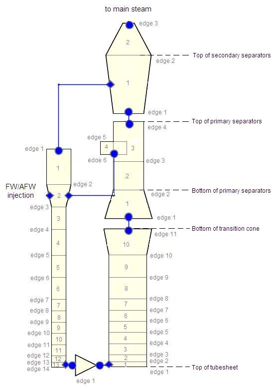
SG Boiler Region — PIPE (10 cells, 11 edges)¶
Component Number = (Loop Number) × 100 + 1410
Cell Layout¶
The boiler region is nodalized consistently with the primary side U-tube component for heat structure thermal coupling. Cells 1 and 19 of the U-tube component are in the tubesheet and do not extend into the boiler region.
| Cells | DX | Description |
|---|---|---|
| 1 | Hdowncomer-to-boiler flow path | Bottom (flow path height) |
| 2 | DXcell2,U-tube − Hflow path | Remainder coupled to U-tube cell 2 |
| 3–9 | DXcells3-9,U-tube | Coupled to primary cells |
| 10 | Hboiler − Σ DX1-9 | Top to transition cone |
Volume — Account for U-tube Displacement¶
where Ntubes = total number of U-tubes (includes both blocked and unblocked).
Edge Geometry¶
| Edge | FA | HD |
|---|---|---|
| 1 | 0.0 (no flow — SJC provides flow path) | 0.0 |
| 2–10 | π/4 · ID²boiler − 2·Ntubes · π/4 · OD²tube | 4 · FAunit cell / (π · ODtube) |
| 11 | π/4 · ID²boiler | IDboiler |
Basis — Appendix A.13
"The hydraulic diameter is calculated based on a unit cell of the SG tube lattice rather than basing it on the total flow area and wetted perimeter across an axial cross section area of the SG. In PWRs, the local conditions on the secondary side of most SG tubes are most accurately defined by the unit cell of the tube lattices."
Friction¶
- NFFedges1,11 = 0; NFFedges2-10 = 1
- KFACedge1 = 0
- KFACedges2-10 = ktube support plates (if known or approximated)
-
KFACedge11 = ktubebank + kexpansion
- ktubebank ≈ 2.0 × (average number of rows crossed), based on staggered tube bank with typical pitch/OD ratio of 1.28
- kexpansion = (1 − FAedge10 / FAedge11)²
Initial Conditions¶
- P = nominal SG pressure
- TL, TV = saturation temperature at SG pressure
- ALPN = plant-specific void distribution, or 0.50 if unknown
- PA = 0.0
Liquid velocity estimate:
where xin = nominal separator inlet quality, ṁFW = nominal feedwater flow.
General Inputs¶
- NSIDES = 1 (for SJC connection); THETA = 90°; IENTRN = 0
- IACC = 0, IPOW = 0
- Use Pipewall = False (HTSTR for U-tube and shroud heat transfer)
SG Downcomer — PIPE (13 cells, 14 edges)¶
Component Number = (Loop Number) × 100 + 1400
The downcomer extends from below the boiler region to the top of the primary separators. It includes the annular region between the SG shell and shroud, plus the volume surrounding the separators.
Basis — Appendix A.13
"The primary consideration in modeling the downcomer was the way that the boiler and separator regions were nodalized, because the heat structure representing the shroud and the separators needs to connect these regions."
The downcomer nodalization is consistent with the boiler region and separator for heat structure coupling. Feedwater injects at the cell including the appropriate elevation (typically near primary separators).
The downcomer connects to:
- Boiler region via SJC (bottom)
- Separator via SEPD side pipe (liquid return)
- Steam dome via side junction (vapor displacement path)
SG Separator — SEPD (4 cells, 6 edges)¶
Component Number = (Loop Number) × 100 + 1415
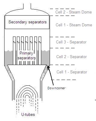
The SEPD component models the upper plenum (transition cone), primary separator, and liquid return path. Phase separation occurs at the secondary separator location.
Cell Layout¶
| Cell | DX | Description |
|---|---|---|
| 1 (main) | Hprimary sep bottom − Htransition cone bottom | Transition cone |
| 2 (main) | Hseparators − 2 · Hswirl vane to top | Lower primary separator |
| 3 (main) | 2 · Hswirl vane to top | Upper primary separator (separation point) |
| 4 (side) | ½ Hseparators − Hswirl vane to top | Liquid return arm |
Volume Formulas¶
- VOLcell1 = π/12 · DX₁ · (ID²lower cone + ID²upper cone + IDlower · IDupper) — conical frustum
- VOLcell2 = Nrisers · DX₂ · π/4 · ID²riser
- VOLcell3 = Nrisers · (DX₃ · π/4 · ID²riser − VOLswirl vanes)
- VOLcell4 = π/4 · (OD²riser opening − ID²riser opening) · DX₄ — annular
Edge Geometry¶
| Edge | FA | HD |
|---|---|---|
| 1 | π/4 · ID²boiler | IDboiler |
| 2–4 | Nrisers · π/4 · ID²riser | IDriser |
| 5–6 (side) | π/4 · (OD²riser opening − ID²riser opening) | (OD² − ID²) / (OD + ID) |
Separator Parameters¶
| Parameter | Value |
|---|---|
| ISTAGE | 0 (ideal separator with constant carryover/carryunder) |
| JCELL | 3 (side tube connects at cell 3 — secondary separator location) |
| NSEPS | 1 (separators lumped as one) |
| NDRYR | 0 (dryers not modeled separately) |
| XCO (carryover) | Plant-specific, or 1.0 × 10⁻³ |
| XCU (carryunder) | Plant-specific, or 5.0 × 10⁻³ |
| ALPSMN | 0.05 (minimum barrel void — avoids oscillation) |
| ALPSMX | 0.9 (maximum barrel void) |
| IENTRN | 0 (offtake model off) |
Basis — Appendix A.13
"The SEPD component is preferred because it allows for greater control over certain aspects of separator performance such as carryover and carryunder. It also avoids use of non-physical modeling artifacts to artificially force the separation of liquid from vapor, such as very high liquid loss coefficients."
"The steam flowing into the main steam line is typically expected to be at least 99.9% vapor, so the carryover is set to a corresponding value (0.001). The phase separation that occurs in the secondary separator is very small compared to the primary separator."
Friction¶
- NFFall edges = 0 (no friction factors — complicated separator geometry)
- KFACedge4 = facility-specified or initially 1.0 (vapor phase through separator)
- KFACedge6 = facility-specified or initially 1.0 (liquid phase through side arm)
- Adjust during steady-state initialization to match target SG pressure drops
SG Steam Dome — PIPE (2 cells, 3 edges)¶
Component Number = (Loop Number) × 100 + 1420
| Cell | DX | VOL |
|---|---|---|
| 1 | Top of primary separator → top of secondary separator | π/4 · ID²upper shell · DX₁ − VOLsecondary separator |
| 2 | Top of secondary separator → SG outlet | 4π/3 · ID²upper shell · DX₂ (ellipsoid) |
| Edge | FA | HD |
|---|---|---|
| 1 | Nrisers · π/4 · ID²riser | IDriser |
| 2 | π/4 · ID²upper shell | IDupper shell or secondary separator HD |
| 3 | π/4 · ID²SG outlet | IDSG outlet |
Basis — Appendix A.13
"There is a side junction connecting the bottom cell of the steam dome region to the upper part of the downcomer to allow for vapor displacement. This side junction is what necessitated the modeling of the steam dome as a separate component, because TRACE does not currently have the capability to model side junctions connecting to any cells in the SEPD component."
Initial Conditions¶
- P = nominal SG pressure
- TL, TV = saturation temperature at SG pressure
- ALPNcell1 = 0.50 or plant-specific; ALPNcell2 = 1.0 (all vapor)
- PA = 0.0
SJC — Downcomer-to-Boiler Flow Path¶
Component Number = (Loop Number) × 100 + 1405
The SJC models the flow path from the bottom of the downcomer to the bottom of the boiler region. Both junction angles should be set to 90°. The offtake model (IENTRN) should be off.
Basis — Appendix A.13
"A SJC component is connected between the two cells via side junctions with the offtake model deactivated. The SJC component can then be used to define the flow path characteristics (flow area, hydraulic diameter, K loss coefficients). The offtake model is not used because the flow path from the downcomer to the boiler region is not consistent with the internal assumption by TRACE that side junctions are cylindrical."
Steady-State Checklist¶
Steady-State Verification
- Primary-side ΔP across SG matches plant data (adjust U-bend KFAC = 50fT if needed)
- Secondary-side pressure equals nominal SG steam dome pressure
- SG thermal power matches target (per-SG value)
- Reactor vessel outlet and inlet temperatures match plant data
- Secondary void distribution is physically reasonable
- Downcomer water level is within expected range
- SG recirculation ratio is consistent with plant design
- 10:1 adjacent cell volume ratio is satisfied throughout
- Separator inlet quality is consistent with plant data
- NPIPES reflects current SG tube plugging level
Cross-References¶
- OTSG Modeling — Once-through SG guidance for B&W plants
- Primary Loop — Hot leg, intermediate leg, RCP connections
- Pressurizer — Pressure control
- Heat Structures — SG tube and shroud HTSTR guidance (§17)
This page faithfully extracts U-tube SG modeling guidance from Rev 1 §4 (primary side) and §13 (secondary side), with associated bases from Appendix A.4 and A.13. The guidance does not consider economizer regions incorporated in more recent SG designs due to relatively limited modeling/assessment experience.