BWR Jet Pump Modeling¶
Source
BWR Modeling Guidance, §9 — Jet Pump Modeling.
Overview¶
This section provides guidance on modeling BWR jet pumps in TRACE using the JETP component. The guidance is applicable to:
- GE BWR/3, BWR/4, BWR/5, and BWR/6
Typical BWR plants have two recirculation loops with 10 jet pumps each. Two JETP components should be created, one per recirculation loop, each representing 10 jet pumps.
Required Inputs¶
- Nominal system pressure
- Nominal core inlet subcooling
- Jet pump throat geometry (ID, length)
- Jet pump diffuser geometry (discharge ID, diffusing length, discharge length)
- Driving nozzle geometry (ID, OD, outlet ID, length, radius of curvature)
- Ram's head driving nozzle assembly geometry (inlet ID, straight section length)
- Recirculation loop mass flow rate
- Driving loop flow ratio (compared to total flow out of jet pump)
- Jet pump material properties (wall roughness)
Component Setup — JETP (7 cells, 9 edges)¶
Cells 1–4 model the main body (throat + diffuser); cells 5–7 model the driving nozzle assembly.
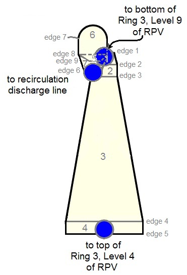
Initialization:
- Main Tube Length = height from diffuser bottom to suction inlet top
- Side Tube Length = pipe length from inlet riser top to driving nozzle outlet
- Main Tube FA = π/4 · ID²diffuser outlet
- Side Tube FA = π/4 · ID²driving nozzle
- NCELL1 = 4 (main body), NCELL2 = 3 (driving nozzle)
- Component Number = (Loop) × 100 + 1030 (pump A) or + 1060 (pump B)
Geometry Inputs¶
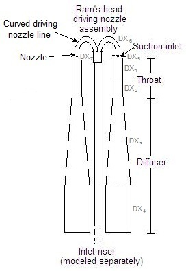
Cell Layout¶
| Cell | DX | VOL |
|---|---|---|
| 1, 2 | ½ throat length | π · DX / 8 · ID²throat |
| 3 | Diffusing section length | π · DX / 12 · (ID²throat + ID²discharge + IDthroat · IDdischarge) — conical frustum |
| 4 | Straight-pipe section at diffuser bottom | π · DX / 4 · ID²discharge |
| 5 | Driving nozzle length | π · DX / 12 · (ID²nozzle line + ID²nozzle outlet + IDline · IDoutlet) — conical frustum |
| 6 | π · Rcurved section | π² / 4 · Rcurve · ID²nozzle line |
| 7 | Straight section of ram's head above inlet riser | π / 8 · Lstraight · ID²ram's head |
- ILEVcells1-7 = −1 (level tracking off — no distinct liquid/gas interface expected)
Edge Geometry¶
| Edge | FA | HD |
|---|---|---|
| 1 (suction inlet) | π/4 · (ID²throat − OD²nozzle) | (ID²throat − OD²nozzle) / (IDthroat + ODnozzle) |
| 2, 3 | π/4 · ID²throat | IDthroat |
| 4, 5 | π/4 · ID²discharge | IDdischarge |
| 6 (nozzle outlet) | π/4 · ID²nozzle outlet | IDnozzle outlet |
| 7 | π/4 · ID²nozzle line | IDnozzle line |
| 8 | min(FAedge7, π/8 · ID²ram's head) | min(IDnozzle line, IDram's head) |
| 9 | π/8 · ID²recirc riser | IDrecirc riser |
Edge 1 Flow Area
FAedge1 may be modified later to obtain the correct ratio of driving to driven flow (M-ratio).
- CCFL: not applied at any edge (LCCFL = 0 for all edges)
Orientation¶
| Edges | GRAV | Direction |
|---|---|---|
| 1–5 (main body) | −1.0 | Downward (flow descends through throat/diffuser) |
| 6–7 (nozzle) | +1.0 | Upward (nozzle drives flow down into throat) |
| 8–9 (ram's head) | −1.0 | Downward |
Initial Conditions¶
| Parameter | Cells 1–4 (body) | Cells 5–7 (nozzle) |
|---|---|---|
| P | Plant-specific suction/discharge P, or nominal system pressure | Plant-specific driving nozzle P, or nominal |
| TL | Plant-specific, or Tsat − ΔTsubcooling | Same |
| TV | Plant-specific, or Tsat | Same |
| ALPN | 0.0 | 0.0 |
| PA | 0.0 | 0.0 |
Initial velocities (if unknown):
where ṁloop = single recirculation loop flow rate, %driving = fraction of total jet pump outlet flow from driving flow, ρ = liquid density at upstream conditions.
Core Inlet Subcooling
If nominal subcooling is not directly available, it can be estimated from: \(h_{core\ inlet} = [h_{FW} \cdot \dot{m}_{FW} + h_{sat} \cdot (\dot{m}_{core} - \dot{m}_{FW})] / \dot{m}_{core}\)
Friction Inputs¶
| Edge | NFF | KFAC | KFACR | ICFLG |
|---|---|---|---|---|
| 1 | 1 | Manufacturer suction loss, or 7.0 (tune to match ΔP) | Manufacturer reverse loss, or 0.0 | 0 |
| 2–4 | 1 | 0.0 | 0.0 | 0 |
| 5 | 1 | Manufacturer discharge loss, or 1.0 (sudden expansion) | Manufacturer reverse, or 0.5 (sudden contraction) | 0 |
| 6 | 1 | 0.0 | 0.0 | 1 (choked flow) |
| 7–8 | 1 | 0.0 | 0.0 | 0 |
| 9 | 1 | 50 fT (close-pattern return bend) | 50 fT | 0 |
Jet Pump Internal Losses
Losses associated with the jet pump nozzle/diffuser geometry are accounted for internally by TRACE. Do not add KFAC values at edges 2–4 and 6–8 to avoid double-counting. KFAC at edge 1 is used to tune the overall jet pump pressure drop.
General Inputs¶
| Parameter | Value |
|---|---|
| JCELL | 1 (driving nozzle connects to top of cell 1) |
| COST | 1.0 (vertical side tube connection) |
| NJETP | 10 (typical for BWR/3-6) |
| EPSDFF | 5.5 (forward diffuser form loss coefficient — use default) |
| EPSDFR | 0.38 (reverse diffuser form loss coefficient — use default) |
| EPSNZF | 5.5 (forward nozzle form loss coefficient — use default) |
| EPSNZR | 0.38 (reverse nozzle form loss coefficient — use default) |
| FINLET | 0.04 (suction form loss — use default) |
| FOUTLET | 0.45 (discharge form loss — use default) |
| ICONC | 0 (no boron in BWR) |
| IPOW | 0 (no fluid power) |
| EPSW | Plant-specific or 4.572 × 10⁻⁵ m |
| Use Pipewall | False (attach HTSTR manually to cells 1–3 for throat/diffuser walls and cells 4–5 for ram's head metal mass) |
EPSDFF, EPSDFR, EPSNZF, EPSNZR
These are not the same as KFAC. They are coefficients used with the diffuser/nozzle angle and area change to compute internal form losses within the JETP component. The default values are recommended.
Steady-State Checklist¶
Steady-State Verification
- Jet pump M-ratio (suction/driving flow) matches plant data (adjust FAedge1 if needed)
- Jet pump ΔP matches plant data (adjust KFACedge1 if needed)
- Core flow rate is correct
- Driving nozzle velocity is physically reasonable
- 10:1 adjacent cell volume ratio is satisfied
Cross-References¶
- Recirculation Lines — Suction/discharge piping, risers, headers
- Recirculation Pump — Pump driving the jet pump system
- Reactor Vessel — Downcomer and lower plenum connections
This page faithfully extracts jet pump modeling guidance from BWR Modeling Guidance §9. The JETP component uses TRACE's specialized jet pump model with internal nozzle/diffuser physics — the analyst primarily needs to specify geometry, NJETP count, and tune edge-1 suction losses for the correct M-ratio.