BWR Containment Modeling
Source
BWR Modeling Guidance — BWR Containment (8-31-16); CONTAN-PIPE Flow Summary (Krotiuk assessment).
Overview
This section provides guidance on modeling BWR primary containment systems in TRACE using the CONTAN component family. The guidance is applicable to:
- Mark I containment
- Mark II containment
- Mark III containment
The CONTAN components model receiving primary-system coolant inventory following a LOCA, providing a heat sink for safety-related equipment, and providing a source of water for ECCS and RCIC systems.
Required Inputs
Drywell
- Dimensions of major shapes (spherical/cylindrical/conical sections — varies by Mark)
- Elevations of major shapes and key positions relative to drywell floor
- Reactor pedestal dimensions
- Radial distance from reactor center to drywell wall
- Free air volume
- Nominal atmospheric conditions (pressure, temperature, relative humidity)
- Gas environment constituents
- Height of downcomers above drywell floor (Mark II)
Suppression Chamber (Wetwell)
- Major structural dimensions (torus thickness for Mark I, chamber height for Mark II)
- Water volume and free air volume
- Number of vent pipes (Mark I and III) or downcomers (Mark I and II)
- Internal design and nominal pressure
- Maximum and minimum water level
- Downcomer depth of submergence
- Suppression pool free-surface area
- Nominal atmospheric conditions
Vent System & Vacuum Breakers
- Hydraulic diameter, area, equivalent length, friction factor for drywell–suppression chamber flow paths
- Minimum ΔP for flow through connecting paths and vacuum breakers
CONTAN Component Structure
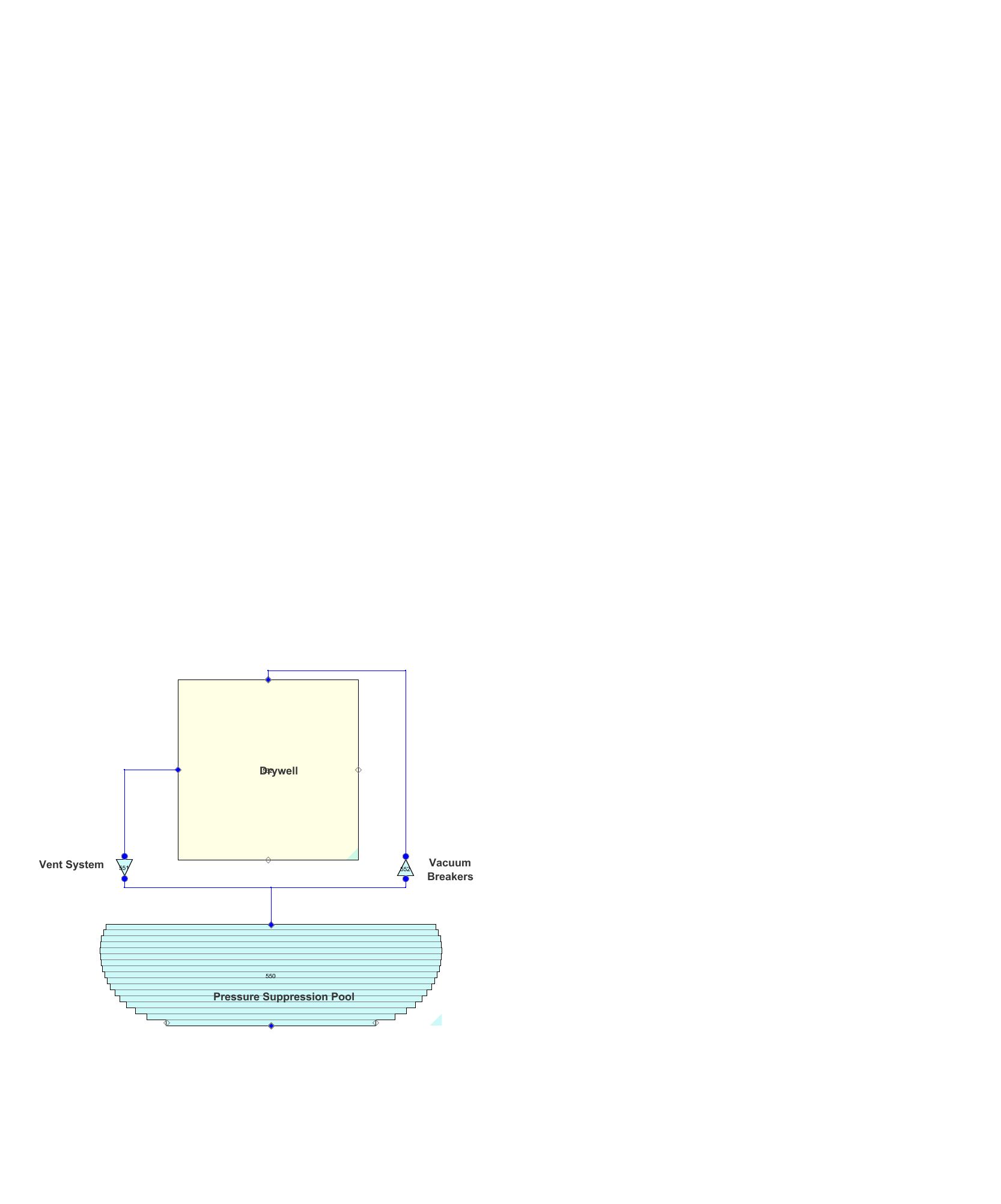
Primary Containment Setup
Two key NAMELIST options control the CONTAN model:
| Parameter | Value | Notes |
|---|---|---|
| LEGACYCONTM | .TRUE. or .FALSE. | .TRUE. = old model; .FALSE. = new model with improved wall HT and droplet field |
| NCONSTANT | 1 | Required for TRACE to perform CONTAN calculations |
New model additional options (LEGACYCONTM = .FALSE.):
| Parameter | Value |
|---|---|
| CONDROPON | Yes/No (droplet field model) |
| ICICONT | No (use explicit solver — semi-implicit increases CPU time significantly) |
| IFULLMEQ | No (extra passive junction momentum equation input) |
General containment options:
| Parameter | Value |
|---|---|
| CSTEP | 1.0 (ratio of CONTAN timestep to thermal-hydraulic DTMAX) |
Drywell — COMPARTMENT
The drywell is modeled as a single large-volume COMPARTMENT. There is no explicit "drywell" designation — the COMPARTMENT functions as a drywell based on its input parameters.
Key inputs:
| Parameter | Description |
|---|---|
| ITRKL | 0 (Off) — pool level tracking not needed for single-cell compartment |
| Spilling Option | Select wetwell compartment (liquid spills to wetwell after accumulating) |
| VOL | Total free volume of drywell |
Free volume estimation (Mark I example):
Internal structure volume can be approximated as ~15% of total geometric volume.
Spill Volume: Volume of liquid that accumulates before spilling to wetwell. For Mark I: volume of spherical segment up to vent pipe elevation minus drywell sump volume.
Wetwell — COMPARTMENT
The wetwell represents the suppression chamber (pool + air space). Same COMPARTMENT component type as drywell, with different parameter values.
Key differences from drywell:
- Has significant liquid region (suppression pool)
- Acts as receiving volume for vent flow
- Provides ECCS suction source
Vents — Passive Junctions
All vent types (Mark I downcomers, Mark II downcomer pipes, Mark III horizontal vents) are modeled as CONTAN Passive Junctions allowing pressure-induced flow between compartments.
- Connect inlet to drywell, outlet to wetwell
- Connection must proceed from Passive Junction to COMPARTMENT (not reverse)
- Connection locations in SNAP do not need to correspond to physical plant locations
Vacuum Breakers — Passive Junctions
Relief valves permitting non-condensable gas flow from wetwell back to drywell:
- Connect inlet to wetwell, outlet to drywell (reverse of vent direction)
- Same Passive Junction modeling approach as vents
Fan Coolers
TRACE employs a fan-cooler model for containment atmosphere cooling. Access via "Containment" → "fan cooler" in SNAP Navigator.
Key inputs:
- Component name, ID, description
- Heat transfer characteristics
- Fan flow rate and trip control
Containment Spray
Containment spray and suppression-pool cooling are functions of the RHRS and are covered in separate guidance.
Known Issue: CONTAN-PIPE BREAK Connection
An NRC staff assessment (Krotiuk) identified issues with BREAK component connections between CONTAN and PIPE components:
- Break flow added directly to CONTAN produces correct mass/energy balances
- Break flow added to a PIPE connected to CONTAN via BREAK shows enthalpy oscillations and energy loss
- Pressures and temperatures are underestimated for PIPE-to-CONTAN flow direction
Recommendation
Ensure high-energy break flow is added directly to the CONTAN component rather than through a PIPE-to-CONTAN BREAK connection. Review all BREAK connections between PIPE and CONTAN components for consistency.
Cross-References
- Break Modeling — BREAK components coupled to CONTAN (IBTY=7)
- Steam Lines — SRV/ADS discharge to suppression pool
- PWR Containment — PWR BREAK BC approach (no PWR-specific CONTAN guidance yet)
This page faithfully extracts BWR containment modeling guidance from the BWR Containment Guidance (8-31-16). The CONTAN component family includes COMPARTMENT (drywell and wetwell), Passive Junctions (vents and vacuum breakers), and fan coolers. Mark I, II, and III containment designs are covered. The explicit numerical solver is recommended over semi-implicit due to CPU time considerations.