BWR Recirculation Line & Valve Modeling
Source
BWR Modeling Guidance — Recirculation Line & Valve Modeling.
Overview
This section provides guidance on modeling BWR recirculation loop piping and valves in TRACE, excluding the recirculation pump (see Recirculation Pump) and jet pumps (see Jet Pump). The guidance is applicable to:
- GE BWR/3, BWR/4, BWR/5, and BWR/6
Each BWR has two recirculation loops supplying flow to 10 jet pumps each. Key design differences between BWR generations:
| Feature | BWR/3 | BWR/4 | BWR/5 & BWR/6 |
|---|---|---|---|
| Flow control | Variable speed pump | Variable speed pump | Constant speed pump + flow control valve |
| Discharge isolation | Valve near pump | Valve near pump | Separate valve near riser |
| Cross-connection | Yes (optional) | No | No |
Break Nodalization
If a recirculation line break is to be modeled, the nodalization for the broken line must be consistent with the Break Modeling guidance. Continue following this guidance for the intact recirculation lines.
Required Inputs
- Recirculation suction line geometry (ID, wall thickness, length, elbow locations)
- Recirculation discharge line geometry (ID, wall thickness, length, elbow locations)
- Discharge manifold geometry (ID, length, wall thickness)
- Riser geometry (ID, length, wall thickness, number of riser pipes, radii of curvature)
- Cross-connection geometry (BWR/3 only: ID, length, wall thickness)
- Discharge isolation valve geometry (seat ID, location, open/close times)
- Flow control valve geometry (BWR/5-6 only: seat ID, location)
- Suction isolation valve geometry (seat ID, location, open/close times)
- Nominal system pressure, full-power loop flow rate, core inlet subcooling
- Nozzle and valve form losses
Component Summary
| Component | Type | Cells/Edges | Comp. Number |
|---|---|---|---|
| Suction line + isolation valve | VALVE | 7 cells, 8 edges | (Loop)×100 + 1425 |
| Flow control valve (BWR/5-6) or discharge isolation (BWR/3-4) | VALVE | 2 cells, 3 edges | (Loop)×100 + 1430 |
| Discharge isolation (BWR/5-6 only) | VALVE | 0 cells | (Loop)×100 + 1430 |
| Discharge riser | PIPE | 7 cells | (Loop)×100 + 1430 |
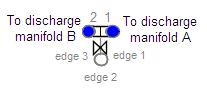
| Cross-connection (BWR/3 only) | PIPE | 2 cells | (Loop)×100 + 1485 |
Suction Line / Suction Isolation Valve — VALVE (7 cells, 8 edges)
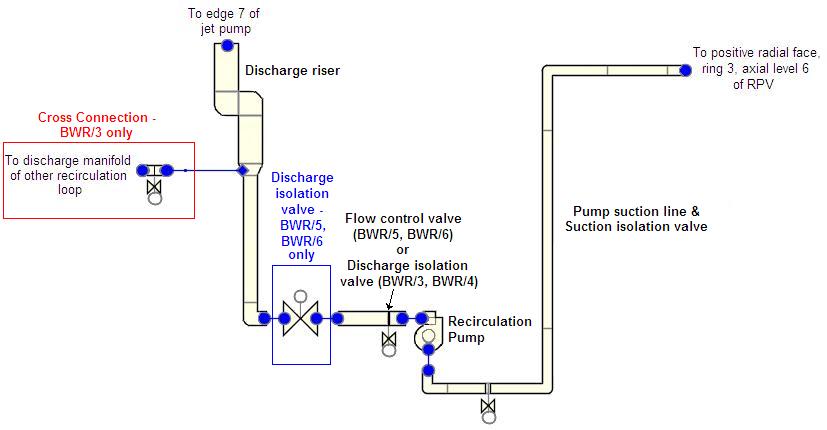
Cell Layout
| Cell | DX | Description |
|---|---|---|
| 1 | Recirc inlet nozzle length | RPV nozzle (frustum) |
| 2 | ½ distance from nozzle to 1st elbow | Horizontal section |
| 3 | Elevation between 1st and 2nd elbows − ½(DX₂+DX₄) | Vertical section |
| 4 | 2× distance from 2nd elbow to valve | Centered on isolation valve |
| 5 | Same as cell 1 | Symmetric with nozzle |
| 6 | Distance from valve to 3rd elbow − ½DX₇ | Post-valve section |
| 7 | 2× distance from 3rd elbow to pump suction inlet | Final horizontal section |
- VOLcell1 = frustum (π·DX/12·[ID²inlet + ID²line + IDinlet·IDline])
- VOLcells2-7 = π/4 · ID²suction line · DX
Edge Geometry
| Edge | FA | HD |
|---|---|---|
| 1 (RPV nozzle) | π/4 · ID²suction inlet | IDsuction inlet |
| 2–5, 7–8 | π/4 · ID²suction line | IDsuction line |
| 6 (valve seat) | π/4 · ID²fully open valve | IDfully open valve |
- CCFL: not applied; all edges LCCFL = 0
Orientation
| Edges | GRAV |
|---|---|
| 1–3, 6–7 (horizontal) | 0.0 |
| 4–5 (vertical down) | −1.0 |
| 8 (vertical up) | +1.0 |
Friction
| Edge | NFF | KFAC | KFACR |
|---|---|---|---|
| 1 | 0 | Manufacturer nozzle loss, or 0.04 (bellmouth from baffle, Idelchik 3-5) | Manufacturer, or 0.68 |
| 2–3, 5, 7–8 | 1 | 0.0 | 0.0 |
| 4, 6, 8 | 1 or 0 | 30 fT (90° standard elbow) | 30 fT |
| 6 (valve) | 0 | Handled by KOPEN table | Handled by KOPEN table |
Valve Inputs
| Parameter | Value |
|---|---|
| IVTY | 3 (flow area table after trip) |
| IVPS | 6 (valve at edge 6) |
| IVTYOV | 0 (flow area fraction per second) |
| INTLOSSOFF | 1 (Off) — due to error with explicit KFAC for fully open valve |
| RVMX | 1 / (valve open/close time) |
| FMINOV / FMAXOV | 0.0 / 1.0 |
| AVLVE | FAsuction isolation valve |
| HVLVE | HDsuction isolation valve |
| FAVLVE | 1.0 (initially open) |
| XPOS | 1.0 |
| VTB1 | [(0.0, 1.0); (closing time, 0.0)] — negative independent variable (time since trip) |
| KOPEN | [(0.0, kvalve); (1.0, kvalve)] where k = manufacturer loss or 2.78 |
| IVSV | Signal variable for problem time |
| IVTR | Trip number for suction isolation |
| IVTROV | 0 (not used) |
Initial Conditions
- P = plant-specific or nominal system pressure
- TL = Tsat − ΔTsubcooling; TV = Tsat
- ALPN = 0.0; PA = 0.0
- VL = ṁloop / (ρ · FAedge); VV = 0.0
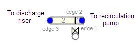
Flow Control / Discharge Isolation Valve — VALVE (2 cells, 3 edges)
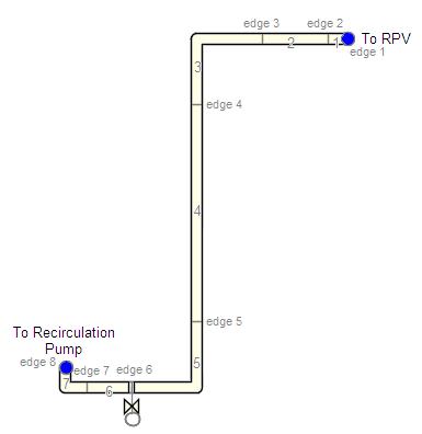
- BWR/3-4: This is the discharge isolation valve
- BWR/5-6: This is the flow control valve
Cell Layout
| Cell | DX (BWR/3-4) | DX (BWR/5-6) |
|---|---|---|
| 1 | Pump outlet to valve | Pump outlet to flow control valve |
| 2 | ⅔ of pipe from valve to 1st elbow | Flow control valve to discharge isolation valve |
- VOL = π/4 · ID²discharge line · DX
Edge Geometry
- FAedges1,3 = π/4 · ID²discharge line
- FAedge2 = π/4 · ID²fully open valve
Valve Inputs
Same IVTY=3 pattern as suction isolation valve. For BWR/5-6 flow control valve, the VTB1/VTB2 tables and trip logic will be different to control flow rate rather than isolate.
Discharge Isolation Valve (BWR/5-6 only) — VALVE (0 cells)
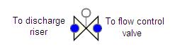
BWR/5-6 plants relocate the discharge isolation valve to near the riser bottom. A zero-cell VALVE component is used:
- NCELLS = 0; HD = IDdischarge line
- IVTY = 3; same trip/table pattern as suction isolation valve
Discharge Riser — PIPE (7 cells)
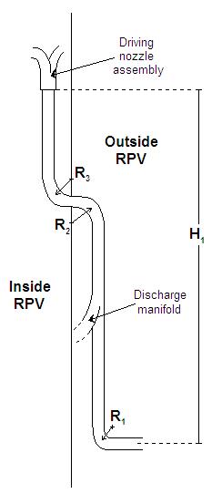
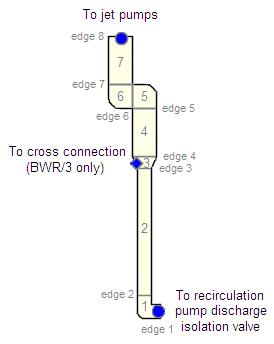
The riser models the complete flow path from the discharge isolation valve/pipe to the bottom of the ram's-head driving nozzle assembly (jet pump component). This includes the discharge manifold and the riser pipes (lumped as a single pipe per loop).
Key Notes
- Total Length calculation includes the elbow curvature corrections: (π/2 − 1) × (R₁ + R₂ + R₃) + H₁
- The horizontal length of the discharge manifold is NOT included in the total length
- Riser pipes above the manifold are lumped as a single pipe per loop
- BWR/3-4: DX starts at ⅓ of pipe from valve to 1st elbow; BWR/5-6: starts at full length from valve
Friction
- 90° elbow losses at appropriate edges: KFAC = 30 fT
- Manifold-to-riser area change losses at tee junction
- NFF = 0 at area change edges; NFF = 1 at pipe sections
Cross-Connection (BWR/3 only) — PIPE (2 cells)
BWR/3 plants can cross-connect discharge manifolds so one pump drives all 20 jet pumps. Model as a 2-cell horizontal PIPE with a valve if needed.
General Notes — All Components
| Parameter | Value |
|---|---|
| ICONC | 0 (no boron in BWR) |
| IPOW | 0 |
| EPSW | Plant-specific or 4.572 × 10⁻⁵ m |
| CCFL | Not applied (LCCFL = 0 at all edges) |
| ICFLG | 0 at all edges |
| Use Pipewall | Per heat structure guidance |
Model Check
Before proceeding, verify that the total length and total elevation change across all recirculation loop components is reasonable compared to the plant. The elevation change from the RPV recirculation inlet to the bottom of the jet pump driving nozzle assemblies must be consistent.
Steady-State Checklist
Steady-State Verification
- Loop flow rate matches nominal full-power value
- Pressure drop across suction line matches plant data
- Pressure drop across discharge line matches plant data
- Total elevation change across loop is correct
- Valve flow areas are consistent with fully open positions
- 10:1 adjacent cell volume ratio satisfied throughout
Cross-References
- Recirculation Pump — PUMP component between suction and discharge lines
- Jet Pump — Driven by riser output
- Break Modeling — Recirculation line break nodalization
- Reactor Vessel — RPV connections
This page faithfully extracts recirculation line and valve modeling guidance from the BWR Modeling Guidance. The recirculation loop includes suction line (VALVE, 7 cells), discharge valve (VALVE, 2 cells or 0 cells), discharge riser (PIPE, 7 cells), and optional BWR/3 cross-connection (PIPE, 2 cells). All valves use IVTY=3 with INTLOSSOFF=1 and KOPEN tables. 90° elbow losses are 30fT; RPV inlet nozzle loss defaults to 0.04 forward / 0.68 reverse.