PWR Pressurizer Modeling¶
Overview¶
This section provides guidance on how to model a typical PWR pressurizer and associated components (surge line, PORVs/SRVs, and pressurizer spray) in TRACE. The guidance applies to the following commercial PWR designs:
- Westinghouse 2-loop PWR
- Westinghouse 3-loop PWR
- Westinghouse 4-loop PWR
- Combustion Engineering 2-loop PWR
- Babcock and Wilcox PWR
The guidance is written assuming the analyst is building the model in SNAP, but corresponding ASCII input variable names are also referenced. Before modeling, ensure all relevant NAMELIST variables are set per Section 1.2 of the Rev 1 guide.
Source
This page is extracted from TRACE PWR Modeling Guidance, Revision 1 (February 2015), Section 11 — PWR Pressurizer Modeling Guidance and Appendix A.11 — Pressurizer.
Component Function¶
The pressurizer maintains primary-system pressure during normal operation and transients. Its model encompasses six related components:
| # | Component | TRACE type | Purpose |
|---|---|---|---|
| 1 | Pressurizer tank | PIPE (IACC = 9, pressurizer type) |
Tank with heaters, spray head, and surge nozzle |
| 2 | Surge line | PIPE (IACC = 0) |
Connection between pressurizer and hot leg |
| 3 | PORVs | VALVE (IVTY = 3, flow-area table after trip) |
Power-Operated Relief Valves, lumped |
| 4 | SRVs | VALVE (IVTY = 3) |
Safety Relief Valves, lumped |
| 5 | PORV/SRV boundary | BREAK | Pressure boundary (containment side) |
| 6 | Spray suction line | PIPE (IACC = 0) |
From cold leg to dome spray head |
| 7 | Spray flow control | PUMP (Pump Type 11, mass-flow-controlled SJC / "TDJ") | Controls spray mass flow |
Required Inputs¶
Required Plant Data Checklist
- Pressurizer liquid temperature
- Pressurizer vapor/gas temperature
- Pressurizer vapor/gas pressure
- Pressurizer liquid volume / level
- Pressurizer geometry (ID, height, total volume)
- Pressurizer material properties (thermal conductivity, heat capacity)
- Pressurizer wall thickness
- Pressurizer wall roughness
- Surge line wall roughness, loss coefficients, material, geometry (L, ID, wall thickness)
- Surge line initial pressure and temperature
- Total pressurizer heater power (maximum)
- Active heater length (from bottom of pressurizer)
- Pressurizer pressure setpoints (for heater/spray control)
- Minimum pressurizer water level (for heater control)
- PORV and SRV rated flow capacities and rated pressures
- PORV/SRV geometry (flow area, hydraulic diameter) and loss coefficients
- PORV/SRV connecting/header line geometry
- PORV/SRV opening and closing setpoints and times
- Pressurizer spray suction wall roughness, loss coefficients, material, geometry
- Pressurizer spray suction line initial pressure and temperature
- Pressurizer spray flow curve (flow as a function of dome pressure)
1 — Pressurizer PIPE Component¶
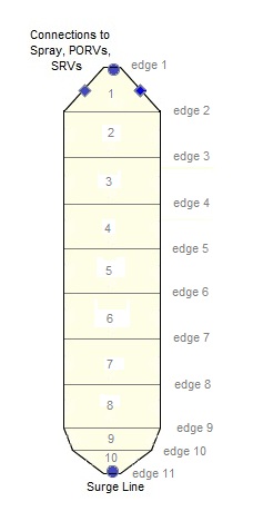
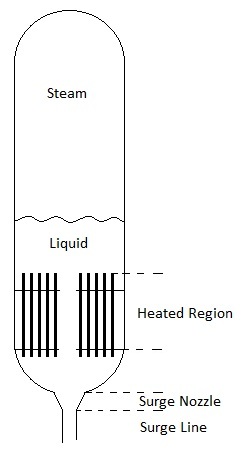
A typical pressurizer tank is modeled with a single PIPE component of 10 cells and 11 edges.
Component Initialization¶
| Input | Value |
|---|---|
| Total Length | \(H_{Pressurizer}\) |
| Hydraulic Diameter (HD) | \(ID_{Pressurizer}\) (overwritten per edge below) |
| Number of Cells (NCELLS) | 10 |
| Number of Pipes (NPIPES) | 1 |
| Orientation | Vertical (can be overridden in the geometry array) |
Naming conventions:
- Component Name (
CTITLE):Pressurizer - Component Number (
NUM):1010
Geometry Inputs¶
The guidance assumes a cylindrical tank with hemispherical caps and heater rods in the lower portion. Determine the height of the heated region (from top of the lower hemispherical cap up to the top of the heater rods) — this defines cells 7 and 8.
Cell Length (DX)¶
Cell Volume (VOL)¶
The volume equations account for the heater-rod displacement in cells 7 and 8:
10:1 Volume Ratio Check
Verify adjacent-cell volume ratios do not exceed 10:1. Adjust DX if needed.
Edge Flow Area (FA)¶
Spray Head FA Heuristic (4400 denominator)
The empirical denominator 4400 sizes the spray head such that the maximum spray flow rate yields a velocity of ~5.5–6.0 m/s at typical PWR conditions — above the 4.0 m/s threshold needed to activate the TRACE PRIZER condensation model, but low enough to avoid unrealistically high velocities in the absence of an explicit droplet-field model.
Edge Hydraulic Diameter (HD)¶
Do not select "Calculate Hydraulic Diam." in SNAP — enter explicitly:
CCFL, Orientation¶
- \(LCCFL_{edges\,1-11} = 0\) (CCFL not expected in pressurizer).
- All edges vertical: \(\theta = -1.571\) rad, \(GRAV = -1.0\).
Initial Conditions¶
The TRACE steady-state solver will re-adjust cell ICs to account for gravitational head effects, so initial values can be approximate.
| Variable | Value |
|---|---|
| \(P_{cells\,1-10}\) | Nominal pressurizer pressure |
| \(TL_{cells\,1-10}\) | Nominal pressurizer liquid temperature (else \(T_{sat}\) at nominal pressure) |
| \(TV_{cells\,1-10}\) | Nominal pressurizer gas temperature (else \(T_{sat}\) at nominal pressure) |
| \(PA_{cell\,1}\) | 0.0 (no NC gas in steam bubble — verify for plant) |
| \(VL_{edges\,1,2}\) | From nominal spray flow rate, or 0.0 |
| \(VL_{edges\,3-11}\), \(VV_{edges\,1-11}\) | 0.0 |
Gas Volume Fraction (ALPN) — Transition Cell¶
The transition cell \(t\) is identified by comparing cumulative cell volumes (from bottom) to \(VOL_{PressurizerLiquid}\):
- If \(VOL_{PressurizerLiquid} < \sum_{n}^{10}VOL_{cell}\) and \(VOL_{PressurizerLiquid} > \sum_{n+1}^{10}VOL_{cell}\), then \(n\) is the transition cell.
Transition Cell Sanity Check
Nominal plant steady-state pressurizer liquid level should place the transition cell somewhere between cells 5 and 9. If it falls outside this range, re-verify the input data.
Friction Inputs¶
Friction Factor Correlation (NFF)¶
Nodalization Criterion
Check the cells adjacent to edges 1 and 11 against the nodalization
criterion in Section 1.5 of the Rev 1 guide (NFF = 0 edges).
Loss Coefficients (KFAC / KFACR)¶
With \(\beta_{1} = ID_{SpraySuctionNozzle}/ID_{PressurizerHead}\) and \(\beta_{11} = ID_{SurgeNozzle}/ID_{PressurizerHead}\):
| Edge | Feature | KFAC | KFACR |
|---|---|---|---|
| 1 | Spray head / sudden expansion | \((1-\beta_{1}^{2})^{2}\) | \(0.5(1-\beta_{1}^{2})\) |
| 2 | SNAP warning suppressor | \(1.0 \times 10^{-10}\) | \(1.0 \times 10^{-10}\) |
| 3–6 | Straight sections | 0.0 | 0.0 |
| 7 | Heater entrance | Plant value, else 0.0 | Plant value, else 0.0 |
| 8 | Heated region | Plant value, else 0.0 | Plant value, else 0.0 |
| 9 | Heater exit | Plant value, else \(1.0 \times 10^{-10}\) | Plant value, else \(1.0 \times 10^{-10}\) |
| 10 | Lower cap | \(1.0 \times 10^{-10}\) | \(1.0 \times 10^{-10}\) |
| 11 | Sudden contraction into surge nozzle | \(0.5(1-\beta_{11}^{2})\) | \((1-\beta_{11}^{2})^{2}\) |
Choked flow is not expected: \(ICFLG_{edges\,1-11} = 0\).
General Inputs¶
| Input | Value | Notes |
|---|---|---|
Solute in coolant (ICONC) |
Per Section 1.6 | — |
Boron concentration (CONC) |
Nominal RCS value (ppm) | — |
Fluid power (IPOW) |
1 (enabled) |
Required with IACC = 9 |
Wall roughness (EPSW) |
Plant value, else \(4.572 \times 10^{-5}\) m | — |
Cross-flow connections (NSIDES) |
2 |
Side junctions for PORV and SRV |
PIPETYPE (IACC) |
9 |
Pressurizer model (enables heater/spray control) |
| Leak paths | 0 |
— |
Side-junction parameters (PORV and SRV side connections):
| Input | Value |
|---|---|
JUNLK |
≠ 0 |
NCMPTO, NCLKTO, NLEVTO |
0 (not a leak path) |
THETA |
0.0° |
IENTRN |
0 (offtake model off) |
Pressurizer Heater Control (IACC = 9)¶
When IACC = 9, TRACE activates the built-in pressurizer heater/spray model.
Required inputs:
| Input | Meaning |
|---|---|
PSET |
Pressure setpoint for heater/spray model |
DPMAX |
Pressure differential at which heater/spray power is at maximum |
ZHTR |
Water level below which the heater/spray model is disabled |
With IPOW = 1 (Fluid Power Option enabled):
| Input | Recommended Value | Meaning |
|---|---|---|
POWIN |
Maximum total heater power | Initial max total power |
POWOFF |
0.0 (unless known) | Power when controlling trip is off after being on |
RPOWMX |
\(1.0 \times 10^{20}\) | Maximum rate of change of power |
POWSCL |
1.0 | Scale factor for optional power-to-fluid table |
POWTB |
Optional | Table of power vs. independent variable |
POWRF |
Optional | Rate factor table |
Legacy FLPOWER Component
Before the IACC = 9 PIPETYPE, pressurizer heater modeling used a
separate FLPOWER component (Component ID 1011, IPOWB = 6 table lookup,
fractional in-beam power distributed to heated cells 7 and 8). The
Rev 1 guidance retains the FLPOWER description for legacy decks. New
models should use IACC = 9 with direct fluid power and delete the
FLPOWER component.
2 — Pressurizer Surge Line PIPE¶
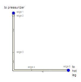
A typical surge line has 4 cells and 5 edges. Many plants do not have the exact "L" shape assumed in the generic nodalization — the analyst is responsible for adapting lengths, orientations, and loss coefficients to the actual plant geometry. The assumed shape was chosen to demonstrate proper minor-loss modeling for elbows.
Component Initialization¶
| Input | Value |
|---|---|
| Total Length | Surge line length |
| Hydraulic Diameter | \(ID_{PressurizerSurgeLine}\) |
| NCELLS | 4 |
| Orientation | Horizontal (overridable per edge) |
CTITLE |
Pressurizer Surge Line |
NUM |
1015 |
Geometry¶
| Parameter | Value |
|---|---|
| \(FA_{edge\,1}\) | \(\tfrac{\pi}{4}ID_{SurgeNozzle}^{2}\) |
| \(FA_{edges\,2-5}\) | \(\tfrac{\pi}{4}ID_{SurgeLine}^{2}\) |
| \(HD_{edge\,1}\) | \(ID_{SurgeNozzle}\) |
| \(HD_{edges\,2-5}\) | \(ID_{SurgeLine}\) |
| \(LCCFL_{edges\,1-5}\) | 0 |
Orientation: edges 1–3 vertical (\(\theta = -1.571\) rad, \(GRAV = -1.0\)); edges 4–5 horizontal (\(\theta = 0\), \(GRAV = 0\)).
Initial Conditions¶
| Variable | Value |
|---|---|
| \(P_{cells\,1-4}\) | Plant SS pressure in surge line, else nominal RCS pressure |
| \(TL_{cells\,1-4}\), \(TV_{cells\,1-4}\) | Plant SS temperatures, else reactor-vessel outlet temperature |
| \(ALPN_{cells\,1-4}\) | 0.0 (all liquid) |
| \(PA_{cells\,1-4}\) | 0.0 |
| \(VL_{edges\,1-5}\), \(VV_{edges\,1-5}\) | 0.0 |
Friction¶
Loss coefficients (with \(\beta_{1} = ID_{SurgeNozzle}/ID_{PressurizerHead}\), \(\beta_{2} = ID_{SurgeLine}/ID_{SurgeNozzle}\), \(\beta_{5} = ID_{SurgeLine}/ID_{HotLeg}\)):
| Edge | Feature | KFAC | KFACR |
|---|---|---|---|
| 1 | Sudden contraction (head → surge nozzle) | \(0.5(1-\beta_{1}^{2})\) | \((1-\beta_{1}^{2})^{2}\) |
| 2 | Sudden contraction (nozzle → line) | \(0.5(1-\beta_{2}^{2})\) | \((1-\beta_{2}^{2})^{2}\) |
| 3 | 90° standard elbow | \(30\,f_{T}\) | \(30\,f_{T}\) |
| 4 | Straight | 0.0 | 0.0 |
| 5 | Sudden enlargement into hot leg | \((1-\beta_{5}^{2})^{2}\) | \(0.5(1-\beta_{5}^{2})\) |
- \(ICFLG_{edges\,1-4} = 0\); \(ICFLG_{edge\,5} = 1\) (choking check at hot-leg exit).
General Inputs¶
ICONC per Section 1.6; CONC = nominal primary-system boron; IPOW = 0;
EPSW plant or default; NSIDES = 0; IACC = 0 (normal pipe); leak paths
off.
3 — PORV and SRV VALVE Components¶
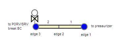
PORVs and SRVs are modeled with the same approach — a 2-cell VALVE representing the piping from the pressurizer to the valve, with edge 3 as the valve interface. All PORVs are lumped into one component and all SRVs into a separate component.
Component Initialization¶
| Input | Value |
|---|---|
| Total Length | Pipe length from pressurizer to valve |
| Hydraulic Diameter | \(ID_{PORV/SRV}\) |
| NCELLS | 2 |
| Orientation | Horizontal |
CTITLE |
Pressurizer PORV or Pressurizer SRV |
NUM |
1020 (PORVs), 1030 (SRVs) |
Alternative: Zero-cell VALVE
If no information is available on the PORV/SRV connecting-line geometry, a zero-cell VALVE may be used instead. Skip the cell geometry section and define only the edge geometry.
Geometry Inputs¶
Edge FA (depends on whether valves share a header or have individual lines):
| Case | \(FA_{edges\,1,2}\) | \(FA_{edge\,3}\) |
|---|---|---|
| Common header | \(\tfrac{\pi}{4}\,ID_{HeaderLine}^{2}\) | \(\tfrac{\pi}{4}\,ID_{OpenValve}^{2} \times N_{valves}\) |
| Individual lines | \(\tfrac{\pi}{4}\,ID_{ConnectingLine}^{2} \times N_{valves}\) | \(\tfrac{\pi}{4}\,ID_{OpenValve}^{2} \times N_{valves}\) |
Edge HD: \(HD_{edges\,1,2} = ID_{ConnectingLine}\); \(HD_{edge\,3} = ID_{OpenValve}\) (single valve).
Orientation: all edges horizontal (\(\theta = 0\), \(GRAV = 0\)).
Initial Conditions¶
| Variable | Value |
|---|---|
| \(P_{cells\,1,2}\) | Nominal pressurizer pressure |
| \(TL_{cells\,1,2}\), \(TV_{cells\,1,2}\) | Nominal pressurizer temperatures |
| \(ALPN_{cells\,1,2}\) | 1.0 (assume all gas if unknown) |
| \(PA_{cells\,1,2}\) | \(P_{nominal} - P_{sat}(T_{gas})\) |
| \(VL\), \(VV\) (all edges) | 0.0 |
Friction¶
- \(ICFLG_{edges\,1,2} = 0\); \(ICFLG_{edge\,3} = 1\) (choked flow expected at valve).
General and Valve Inputs¶
| Input | Value | Notes |
|---|---|---|
ICONC |
Per Section 1.6 | — |
CONC |
0.0 ppm | No liquid initially |
IVTY |
3 — Flow Area Table After Trip |
— |
IPOW |
0 | — |
EPSW |
Plant or default | — |
IVPS |
Edge 3 of 3 | — |
IVTYOV |
0 — Flow Area Fraction/sec | — |
INTLOSSOFF |
1 — Off |
Internal loss model turned off (known model error when used with explicit KFAC for fully-open PORV/SRV) |
RVMX, RVOV |
\(1 / t_{open/close}\) | — |
FMINOV, FMAXOV |
0.0 / 1.0 | — |
AVLVE |
\(FA_{edge\,3}\) | — |
HVLVE |
\(HD_{edge\,3}\) | — |
FAVLVE, XPOS |
0.0 | Initially closed |
VTB1 |
[(0.0, 0.0); (t_open, 1.0)] |
Opening-time table |
VTB2 |
[(0.0, 0.0); (t_close, 1.0)] |
Closing-time table |
KOPEN |
[(0.0, KFAC_valve); (1.0, KFAC_valve)] |
Form-loss table |
IVSV |
Signal variable for problem time (negative sign) | — |
IVTR |
Trip number for PORV/SRV setpoint | — |
IVTROV |
0 | Override trip not used |
KFAC_valve = manufacturer forward loss coefficient for the fully open
valve. If only \(C_{v}\) is known, use the conversion from Crane TP-410 p. 2-10.
If no data is available, 2.78 is a reasonable estimate for typical nuclear
valves.
PORV/SRV Trip Setup¶
The trip that activates the valve uses four setpoints with a reverse-enabled hysteresis band:
| Setpoint | Value |
|---|---|
1 (SETP) |
PORV/SRV closing pressure setpoint |
2 (SETP) |
Average of setpoints 1 & 4, minus 0.1 % |
3 (SETP) |
Average of setpoints 1 & 4 |
4 (SETP) |
PORV/SRV opening pressure setpoint |
- Setpoint Range Type: 3 —
ON(For) || OFF || On(Rev) - Initial Set-Status: Off
- Signal Type (
ITST): 1 — Signal Variable - Reverse Trip: True
- Setpoint delays: opening delay on Delay 1, closing delay on Delay 4
Flow Capacity Verification¶
After the PORV/SRV VALVE is built, verify it achieves the correct flow rate at the appropriate rated pressure(s) per Section 1.8 of the Rev 1 guide.
4 — PORV/SRV BREAK Boundary Condition¶
Each PORV or SRV VALVE discharges directly into a BREAK component representing the containment pressure boundary.
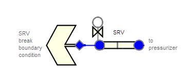
Naming: CTITLE = Pressurizer PORV/SRV Pressure Boundary Condition;
NUM = 1025 (PORV BREAK), 1035 (SRV BREAK).
Break Type (IBTY)¶
IBTY |
Use |
|---|---|
0 — No tables |
Constant containment pressure — default when flow is expected to remain choked (backpressure unimportant) |
1 — Input pressure table |
Pressure vs. time — needed when flow may become subsonic (long-term cooling) |
7 — CONTAN component |
Couple to CONTAN; fluid properties set by CONTAN (guidance for CONTAN with PWR not yet provided in Rev 1) |
Boundary-Condition Inputs¶
| Input | Value |
|---|---|
ISAT |
3 — set liquid and gas to \(T_{sat}\) |
IOFF |
0 — last interpolated state held constant |
DXIN |
\(10^{-6}\) m (small, so junction properties weight toward upstream volume) |
VOLIN |
\(10^{6}\) m³ (large, same reason) |
ALPN |
1.0 (all vapor at transient start) |
TIN |
Initial containment temperature |
PIN |
Initial containment pressure |
PAIN |
Initial containment pressure |
ADJPRESS |
False — do not tie BREAK pressure to upstream cell |
RBMX |
\(10^{20}\) Pa/s |
PSCL |
1.0 |
For IBTY = 1: PTB is a pressure-vs-time table covering the full
transient (no extrapolation). IBSV = signal variable corresponding to
problem time; IBTR = optional trip to start table evaluation.
For IBTY = 7 (CONTAN): |COMPID| = CONTAN component ID;
compartment region = Liquid Space (negative COMPID) since PORVs/SRVs
typically discharge below the containment water surface for steam cooling.
BDSPRAY = 0.0; BDCOND = assumed mass fraction of steam reaching thermal
equilibrium with containment liquid.
5 — Pressurizer Spray Suction Line PIPE¶
A 5-cell, 6-edge PIPE from the cold leg to the pressurizer steam dome, connected via the side junction on the cold leg.
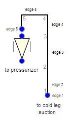
Component Initialization¶
| Input | Value |
|---|---|
| Total Length | Spray suction line length |
| Hydraulic Diameter | \(ID_{SpraySuctionLine}\) |
| NCELLS | 5 |
| Orientation | Vertical |
CTITLE |
Pressurizer Spray Suction Line |
NUM |
1040 |
Geometry¶
The first and last cell lengths are fixed at \(0.625 \times D_{SpraySuctionLine}\)
to satisfy the friction nodalization criterion at NFF = 0 edges:
| Parameter | Value |
|---|---|
| \(FA_{edges\,1-5}\) | \(\tfrac{\pi}{4}ID_{SpraySuctionLine}^{2}\) |
| \(FA_{edge\,6}\) | \(FA_{edge\,1,\,PressurizerDome}\) (consistent with top-of-dome edge) |
| \(HD_{edges\,1-5}\) | \(ID_{SpraySuctionLine}\) |
| \(HD_{edge\,6}\) | \(HD_{edge\,1,\,PressurizerDome}\) |
| \(LCCFL_{edges\,1-6}\) | 0 |
Orientation: edges 1–4 vertical upward (\(\theta = +1.571\), \(GRAV = +1.0\)); edge 5 horizontal; edge 6 vertical downward (\(\theta = -1.571\), \(GRAV = -1.0\)).
Initial Conditions¶
| Variable | Value |
|---|---|
| \(P_{cells\,1-5}\) | Plant SS pressure in suction line, else cold leg SS, else nominal RCS |
| \(TL\), \(TV\) | Plant SS temperature, else cold leg SS, else reactor vessel inlet |
| \(ALPN_{cells\,1-5}\) | 0.0 (all liquid) |
| \(PA\) | 0.0 |
| \(VL_{edges\,1-6}\) | From max spray flow, or 0.0 |
| \(VV_{edges\,1-6}\) | 0.0 |
Friction¶
With \(\beta = ID_{SpraySuctionLine}/ID_{ColdLeg}\):
| Edge | Feature | KFAC | KFACR |
|---|---|---|---|
| 1 | Sudden contraction (cold leg → line) | \(0.5(1-\beta^{2})\) | \((1-\beta^{2})^{2}\) |
| 2–3 | Straight | 0.0 | 0.0 |
| 4, 5 | 90° standard elbows | \(30\,f_{T}\) | \(30\,f_{T}\) |
| 6 | (Consistent with pressurizer dome edge 1) | \(KFAC_{edge\,1,\,Press}\) | \(KFACR_{edge\,1,\,Press}\) |
\(ICFLG_{edges\,1-6} = 0\).
General and Connection Inputs¶
ICONC per Section 1.6; CONC = nominal RCS boron; IPOW = 0; EPSW
plant/default; IACC = 0; leak paths off.
NSIDES = 0 on the spray suction line itself, but increment the cold
leg's NSIDES by 1 for the side junction. On the cold-leg side junction:
JUNLK ≠ 0; NCMPTO = NCLKTO = NLEVTO = 0; THETA = plant angle (else
90°); IENTRN = 1 (offtake model on — required for the side
junction).
6 — Pressurizer Spray TDJ (PUMP)¶
SNAP labels this a "TDJ" but TRACE models it as a PUMP component. It provides the boundary between the spray suction line and the pressurizer dome, delivering a controlled mass flow.
| Input | Value |
|---|---|
| Pump Type | 11 — Mass Flow Controlled (SJC) |
| Hydraulic Diameter | \(ID_{SpraySuctionLine}\) (overwritten) |
| Orientation | Vertical (downward into dome: \(\theta = -1.571\), \(GRAV = -1.0\)) |
CTITLE |
Pressurizer Spray |
NUM |
1045 |
Edge Geometry¶
- \(FA_{edge\,1} = FA_{edge\,1,\,Pressurizer}\)
- \(HD_{edge\,1} = HD_{edge\,1,\,Pressurizer}\)
- \(LCCFL_{edge\,1} = 0\)
- \(KFAC_{edge\,1}\), \(KFACR_{edge\,1}\): consistent with pressurizer edge 1
- \(NFF_{edge\,1} = 0\); \(ICFLG_{edge\,1} = 0\)
Initial Conditions¶
- \(VL_{edge\,1} = VL_{edge\,1,\,Pressurizer}\)
- \(VV_{edge\,1} = 0.0\)
Control Inputs¶
| Input | Value |
|---|---|
ICBVL (liquid mass flow control) |
Control-block ID for spray flow controller |
ICBVV (vapor mass flow control) |
0 (no vapor flow) |
VLLIM |
Max liquid flow, else \(10^{20}\) |
VVLIM |
Max vapor flow, else \(10^{20}\) |
Spray Control Block (Type 102 — Function):
| Input | Value |
|---|---|
Gain (CBGAIN) |
1.0 |
Min / Max (CBXMIN / CBXMAX) |
\(-10^{20}\) / \(+10^{20}\) |
Constant 2 (CBCON2) |
0.0 |
Function table (CBTB1) |
Data pairs of [dome pressure (Pa), flow rate (kg/s)] — from plant spray curve |
Input (ICB1) |
Signal variable for pressurizer dome pressure |
Dome-Pressure Signal Variable:
| Input | Value |
|---|---|
CTITLE |
Pressurizer Dome Pressure |
Signal (ILCN) |
Pressurizer PIPE component ID (1010), cell 1 |
| Behavior Mode | Exact Value |
Parameter Type (ISVN) |
21 — Pressure |
Geometry Input Summary¶
Table 11.9-1 — Pressurizer PIPE¶
With \(\beta_{1} = ID_{SprayNozzle}/ID_{PressurizerHead}\) and \(\beta_{11} = ID_{SurgeNozzle}/ID_{PressurizerHead}\):
| Node | DX | VOL | Edge | FA | HD | GRAV | KFAC | KFACR | NFF | ICFLG |
|---|---|---|---|---|---|---|---|---|---|---|
| 1 | \(\tfrac{1}{2}ID_{Head}\) | \(\tfrac{1}{12}\pi ID_{Head}^{3}\) | 1 | spray area † | \(\sqrt{4FA_{1}/\pi}\) ‡ | −1.0 | \((1-\beta_{1}^{2})^{2}\) § | \(0.5(1-\beta_{1}^{2})\) § | 0 | 0 |
| 2 | \(\tfrac{1}{5}(H_{press}-H_{htd}-ID_{Head})\) | \(DX_{2} \cdot FA_{2}\) | 2 | \(\pi ID_{2}^{2}/4\) | \(ID_{Press}\) | −1.0 | 1.0E-10 | 1.0E-10 | 0 | 0 |
| 3 | \(\tfrac{1}{5}(\ldots)\) | \(DX_{3} \cdot FA_{3}\) | 3 | \(\pi ID_{3}^{2}/4\) | \(ID_{Press}\) | −1.0 | 0.0 | 0.0 | 1 | 0 |
| 4 | \(\tfrac{1}{5}(\ldots)\) | \(DX_{4} \cdot FA_{4}\) | 4 | \(\pi ID_{4}^{2}/4\) | \(ID_{Press}\) | −1.0 | 0.0 | 0.0 | 1 | 0 |
| 5 | \(\tfrac{1}{5}(\ldots)\) | \(DX_{5} \cdot FA_{5}\) | 5 | \(\pi ID_{5}^{2}/4\) | \(ID_{Press}\) | −1.0 | 0.0 | 0.0 | 1 | 0 |
| 6 | \(\tfrac{1}{5}(\ldots)\) | \(DX_{6} \cdot FA_{6}\) | 6 | \(\pi ID_{6}^{2}/4\) | \(ID_{Press}\) | −1.0 | 0.0 | 0.0 | 1 | 0 |
| 7 | \(\tfrac{1}{2}H_{htd}\) | \(DX_{7} \cdot FA_{7}\) ‖ | 7 | \(\pi ID_{7}^{2}/4\) | \(ID_{Press}\) | −1.0 | 0.0 ‖ | 0.0 ‖ | 1 | 0 |
| 8 | \(\tfrac{1}{2}H_{htd}\) | \(DX_{8} \cdot FA_{8}\) ‖ | 8 | \(\pi ID_{8}^{2}/4\) | \(ID_{Press}\) | −1.0 | 0.0 ‖ | 0.0 ‖ | 1 | 0 |
| 9 | \(\tfrac{1}{4}ID_{Head}\) | \(DX_{9} \cdot FA_{9}\) | 9 | \(\pi ID_{9}^{2}/4\) | \(ID_{Press}\) | −1.0 | 1.0E-10 ‖ | 1.0E-10 ‖ | 0 | 0 |
| 10 | \(\tfrac{1}{4}ID_{Head}\) | \(\tfrac{\pi DX_{9}}{6}\left(\tfrac{3}{4}ID_{Head}^{2}-2DX_{9}^{2}\right)\) | 10 | \(\pi\left(\tfrac{1}{4}ID_{Head}^{2}-DX_{9}^{2}\right)\) | \(2\sqrt{\tfrac{1}{4}ID_{Head}^{2}-DX_{9}^{2}}\) | −1.0 | 1.0E-10 | 1.0E-10 | 0 | 0 |
| 11 | \(\pi ID_{surgenozzle}^{2}/4\) | \(ID_{surgenozzle}\) | −1.0 | \(0.5(1-\beta_{11}^{2})\) | \((1-\beta_{11}^{2})^{2}\) | 0 | 0 |
† \(FA_{1}\) = spray head area if known/modeled, else the 4400-based heuristic, else 0.0. ‡ \(HD_{1} = 1.0 \times 10^{10}\) if \(FA_{1} = 0\). § \(KFAC_{1} = KFACR_{1} = 0.0\) if \(FA_{1} = 0\). ‖ Plant-specific heater-region loss coefficients may be used if available; volume equations in cells 7–8 subtract the heater-rod displacement. EPSW = plant value, else \(4.572 \times 10^{-5}\) m.
Table 11.9-2 — Pressurizer Surge Line¶
With \(\beta_{1} = ID_{SurgeNozzle}/ID_{PressurizerHead}\), \(\beta_{2} = ID_{SurgeLine}/ID_{SurgeNozzle}\), \(\beta_{5} = ID_{SurgeLine}/ID_{HotLeg}\):
| Node | DX | VOL | Edge | FA | HD | GRAV | KFAC | KFACR | NFF | ICFLG |
|---|---|---|---|---|---|---|---|---|---|---|
| 1 | \(L_{surgenozzle}\) | \(\pi ID_{1}^{2}DX_{1}/4\) | 1 | \(\pi ID_{1}^{2}/4\) | \(ID_{surgenozzle}\) | −1.0 | \(0.5(1-\beta_{1}^{2})\) | \((1-\beta_{1}^{2})^{2}\) | 0 | 0 |
| 2 | \(L_{tot}/3\) | \(DX_{2}\cdot FA_{2}\) | 2 | \(\pi ID_{2}^{2}/4\) | \(ID_{surgeline}\) | −1.0 | \(0.5(1-\beta_{2}^{2})\) | \((1-\beta_{2}^{2})^{2}\) | 0 | 0 |
| 3 | \(L_{tot}/3\) | \(DX_{3}\cdot FA_{3}\) | 3 | \(\pi ID_{3}^{2}/4\) | \(ID_{surgeline}\) | −1.0 | \(30\,f_{T}\) | \(30\,f_{T}\) | 1 | 0 |
| 4 | \(L_{tot}/3\) | \(DX_{4}\cdot FA_{4}\) | 4 | \(\pi ID_{4}^{2}/4\) | \(ID_{surgeline}\) | 0.0 | 0.0 | 0.0 | 1 | 0 |
| 5 | \(\pi ID_{5}^{2}/4\) | \(ID_{surgeline}\) | 0.0 | \((1-\beta_{5}^{2})^{2}\) | \(0.5(1-\beta_{5}^{2})\) | 0 | 1 |
\(L_{tot}\) = surge line total length; \(f_{T}\) from Table 1.5-1.
Modeling Basis (Appendix A.11)¶
Why PIPE with IACC = 9 instead of PRIZER
The preferred pressurizer component is historically the PRIZER component, which includes a condensation model, a simple heater model (direct energy deposition into liquid), and a specialized steady-state mode maintaining pressurizer level during primary-loop flow excursions. However, PRIZER does not allow side junctions, so PORVs, SRVs, and the spray cannot connect to the top of a PRIZER component.
A code modification was developed to move the PRIZER models into the
PIPE component via IACC = 9, also improving the heater control to
better mimic actual plant response. This modification missed the Patch 3
release, so legacy decks use a PIPE + FLPOWER pair. The condensation
model generally has minimal impact on TRACE analyses and is not fully
representative of the physical process (no droplet field). For current
work, a single PIPE with IACC = 9 and IPOW = 1 is recommended, and
FLPOWER can be deleted.
Heater rod modeling
The pressurizer is idealized as a cylindrical tank with spherical caps, with the bottom cap sub-divided (cells 9–10) to help satisfy the 10:1 volume criterion. Heater rods could be modeled explicitly as heat structures, but their thermal mass is usually small and they don't play a significant role in most transients — so direct energy deposition into the fluid is satisfactory. Rod liquid displacement is included in the cell volume calculations, and flow resistance (if known) enters as form losses; the rods are otherwise ignored.
Steady-state initialization recommendation
The recommended approach is to connect the pressurizer to a BREAK pressure boundary condition to hold system pressure at the target during steady-state initialization, optionally with a zero-cell VALVE to allow isolation. After SS runs, adjust water level if needed, isolate/remove the BREAK, and re-run to confirm all parameters are on target. This is more stable than using the heater to hold pressure.
Level tracking and offtake
Level tracking should be activated in the pressurizer tank due to the
well-defined water level. In this guidance, PORVs/SRVs connect via side
junctions with the offtake model activated, which causes TRACE to
internally enable pressurizer level tracking without needing to enter the
ILEV array for all 1-D components. Typically the offtake model isn't
"needed" because the water level won't reach the PORV/SRV elevation —
but activating it is a convenient way to trigger level tracking.
Non-condensable gases
Even though the initial pressurizer void contains steam at SS, typical PWR plants do not contain air or other NCs in the pressurizer — plant initial heatup starts with the pressurizer full of liquid. Consequently, the recommended model uses no NC partial pressures in the pressurizer. (The TRACE model is not initialized from cold, so this differs from the physical plant startup.)
Surge line, spray, and PORV/SRV cautions
- The surge line's exact geometry (number of bends, directions) varies by plant. The generic "L" shape is illustrative; the analyst must adapt orientations and loss coefficients to the actual plant.
- The pressurizer spray is often omitted from PWR models but may be needed to obtain a correct steady-state heat balance. TRACE lacks an explicit droplet-field model, so spray-dependent results must be evaluated carefully. The spray suction line becomes a dead-end when the spray is inactive — this can cause numerical oscillations, so the PIPE and TDJ may be isolated or deleted if they cause convergence problems.
- Multiple PORVs or SRVs are lumped into single VALVE components with summed flow areas and volumes but HD based on a single valve. Both common-header and individual-line configurations are supported. For most short transients, the BREAK pressure is unimportant because flow through the valves is choked; if flow may become subsonic, the BREAK pressure becomes important and a pressure table or CONTAN coupling should be used.
See Appendix A.23 for generic thermal-hydraulic component discussion.
References¶
- TRACE PWR Modeling Guidance, Revision 1, U.S. NRC, February 2015 — Section 11 and Appendix A.11.
- TRACE V5.0 Theory Manual, U.S. NRC, ADAMS ML120060218.
- TRACE V5.0 User's Manual, Volume 2: Modeling Guidelines, U.S. NRC, ADAMS ML120060402 (PRIZER component, FLPOWER component).
- Crane Technical Paper No. 410, Flow of Fluids Through Valves, Fittings, and Pipe.
Related Topics¶
Extracted from TRACE PWR Modeling Guidance, Rev 1 (Feb 2015), §11 and App. A.11. No substantive discrepancies were found between the Rev 1 PDF and the corresponding component source (Historical-Rev_1/Pressurizer.docx).