BWR Control Rod Guide Tube Modeling
Source
BWR Modeling Guidance — Control Rod Guide Tube Modeling.
Overview
This section provides guidance on modeling BWR control rod guide tubes (CRGTs) and the associated CRD cooling flow in TRACE. CRGTs are modeled as PIPE components with connected FILL components for CRD cooling flow. The guidance is applicable to:
- GE BWR/3, BWR/4, BWR/5, and BWR/6
Two CRGT PIPE components (with accompanying FILL components) should be included in the model, representing the CRGTs associated with Rings 1 and 2 of the RPV VESSEL component.
Required Inputs
- Axial heights of lower 7 levels in RPV VESSEL component
- Flow area of edge connecting axial levels 8 & 9 in RPV (Rings 1, 2)
- CRGT inner diameter (ID)
- Total number of CRGTs
- Number of fuel assemblies in Rings 1 & 2 of RPV
- Control blade wing geometry (thickness, width)
- Leakage flow area at bottom of CRGT
- Fuel support piece flow area (unorificed center channel)
- Nominal system pressure and core inlet subcooling
- Nominal total CRD cooling flow rate and liquid temperature
- CRD cooling flow coastdown time
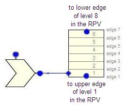
Component Setup — PIPE (6 cells, 7 edges)
Initialization:
- Total Length = Σ DZi,RPV for levels 2 through 7
- NCELLS = 6
- NPIPES:
- Ring 1: (Nfuel assemblies Ring1 / 2·Ntotal fuel assemblies) × Ntotal CRGTs, rounded
- Ring 2: 0.5 × Ntotal CRGTs − NPIPESRing1
- Orientation = Vertical
Geometry
Cell Layout
- DXcell i = DZi+1,RPV (cell heights match RPV axial levels)
Volume — Account for Control Blade Displacement
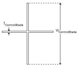
Square-tipped blades:
Rounded-tipped blades:
where w = blade width, t = blade thickness.
10:1 Volume Ratio
The 10:1 check is generally not applied for connections between 1-D and 3-D cells. Check cells 2–5 for compliance. If adjustments are needed, subdivide existing cells rather than modifying them (to simplify heat structure setup later).
Edge Geometry
| Edge | FA | HD |
|---|---|---|
| 1 (bottom leakage) | Leakage flow area at bottom of CRGT | 2 · FAedge1 / (π · IDCRGT) |
| 2–6 | Same as VOL/DX (blade displacement formula) | 4 · FA / (π · IDCRGT + 4 · wblade) |
| 7 (fuel support piece) | FAfuel support center channel − blade displacement | 4 · FA / [(π−8)·R + 4·H + 4·wblade] |
Fuel Support Piece FA
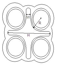
If the actual flow area is not available, it can be approximated from measurements as: FA = 2·W·H − W² + (4−π)·R² where W, H, R are as shown in Figure 1.1-1.
CCFL at Top (Edge 7)
CCFL may occur at the top of the CRGTs due to countercurrent flow:
| Parameter | Value |
|---|---|
| CBETA | 1.0 (Kutateladze correlation) |
| CCFLM | 1.0 |
| CCFLC | 2.0493902 |
- LCCFLedges1-6 = 0
- LCCFLedge7 = CCFL model "N"
Orientation
All edges vertical upward: GRAV = +1.0
Initial Conditions
- P = plant-specific or nominal system pressure
- TL = Tsat − ΔTsubcooling; TV = Tsat
- ALPN = 0.0; PA = 0.0
- VLedge1 = 0.0 (assume all CRD flow exits through top)
- VLedges2-7 = ṁCRD cooling / (Ntotal CRGTs · ρ · FAedge)
- VV = 0.0
Friction
| Edge | NFF | KFAC | KFACR | ICFLG |
|---|---|---|---|---|
| 1 | 0 | 0.5·(1−β₁²) + (1−β₂²)² | 0.5·(1−β₁²) + (1−β₂²)² | 0 |
| 2–6 | 1 | 0.0 | 0.0 | 0 |
| 7 | 0 | 0.5·(1−β₁²) + (1−β₂²)² | 0.5·(1−β₁²) + (1−β₂²)² | 0 |
- Edge 1: β₁ ≈ 0, β₂² = FAedge1/FAedge2
- Edge 7: β₁² = FAedge7/FAedge6, β₂² = FAedge7/FAcore axial edge
KFAC Tuning
Edge 1 and 7 KFAC/KFACR values may need adjustment to obtain correct flow distribution due to a bias in TRACE's momentum calculation for this type of geometry.
General Inputs
- ICONC = 0 (or per guidance); CONC = 0.0
- IPOW = 0; EPSW = plant-specific or 4.572 × 10⁻⁵ m
- NSIDES = 1 (for CRD cooling flow FILL connection); THETA = 0°; IENTRN = 0
- IACC = 0; Use Pipewall = per heat structure guidance
CRD Cooling Flow — FILL Component
Setup
| Parameter | Value |
|---|---|
| IFTY | 8 (mass flow with trip) |
| IOFF | 2 (state properties held constant) |
| DXIN | DXCRGT,cell1 |
| VOLIN | VOLCRGT,cell1 |
| ALPIN | 0.0 |
| TLIN | CRD cooling flow temperature (after CRD seals) |
| TVIN | Tsat at input pressure |
| PIN | CRD cooling water pressure, or nominal system pressure |
| PAIN | 0.0 |
| CONCIN | 0.0 |
| TWTOLD | 0.0 |
| RFMX | 10²⁰ (no restriction on rate change) |
| Couple to CONTAN | False |
| VMSCL | 1.0 |
Initial Mass Flow
Set FLWOFF = FLOWIN (prevents confusion when controlling trip returns to OFF).
Fill Table (VMTBM)
The independent variable form should be set to negative (time since trip). Typical scenarios:
- CRD cooling termination: VMTBM = [(0.0, FLOWIN); (rampdown time, 0.0)]
- Operator action: Table of flow values as a function of time after trip
Trip Setup
For a simple trip to terminate CRD cooling at transient initiation:
| Parameter | Value |
|---|---|
| Setpoint Range Type | 1 [On(For) || OFF] |
| Initial SET | 0 (On) |
| SETP1 | −1.0 |
| SETP2 | 0.0 |
| ITST | 1 (Signal Variable) |
| IDSG | Signal variable for problem time |
| Reverse Trip | False |
Cross-References
- Reactor Vessel — RPV VESSEL component that CRGTs connect to
- Steam Separators — Upper RPV flow paths
This page faithfully extracts CRGT and CRD cooling flow modeling guidance from the BWR Modeling Guidance. CRGTs are PIPE components with 6 cells matching RPV axial levels 2–7, with CCFL at the top edge (Kutateladze, CCFLC=2.049) and FILL-driven CRD cooling flow entering via side junction.