PWR Primary Loop Modeling¶
Overview¶
This section provides guidance on how to model the primary loop piping and reactor coolant pumps (RCPs) for a typical PWR in TRACE. The guidance covers the hot leg, intermediate leg (SG-outlet to RCP-inlet), RCP, and cold leg for both U-Tube SG plants and Once-Through SG (OTSG / B&W) plants. Steam generator modeling is covered separately in the Steam Generator page.
The guidance applies to:
- Westinghouse 2-loop PWR
- Westinghouse 3-loop PWR
- Westinghouse 4-loop PWR
- Combustion Engineering 2-loop PWR
- Babcock and Wilcox (B&W) PWR
Before starting, ensure all relevant NAMELIST variables are set per Section 1.2 of the Rev 1 guide.
Source
This page is extracted from TRACE PWR Modeling Guidance, Revision 1 (February 2015), Sections 3 (UTSG Hot Leg), 5 (UTSG Intermediate Leg), 6 (OTSG Hot Leg), 8 (OTSG Intermediate Leg), 9 (RCP), 10 (Cold Leg), and Appendix A sections A.3–A.10.
Loop Components¶
| # | Component | TRACE type | NCELLS | NUM pattern |
Purpose |
|---|---|---|---|---|---|
| 1 | Hot Leg | PIPE (IACC = 0) |
6 (UTSG), 10 or 12 (OTSG) | Loop# × 100 + 1000 |
RPV outlet nozzle → SG inlet nozzle |
| 2 | Intermediate Leg | PIPE (IACC = 0) |
7 (UTSG), 6 (OTSG lowered), 2 (OTSG raised) | Loop# × 100 + 1020 |
SG outlet nozzle → RCP suction nozzle |
| 3 | RCP Suction Nozzle | PIPE (IACC = 0) |
1 | Loop# × 100 + 1025 (A), + 1055 (B) |
Pump suction pipe |
| 4 | Reactor Coolant Pump | PUMP (IPMPTY = 2) |
2 | Loop# × 100 + 1030 (A), + 1060 (B) |
Centrifugal RCP + discharge nozzle |
| 5 | Cold Leg | PIPE (IACC = 0) |
6 | Loop# × 100 + 1035 |
RCP discharge nozzle → RPV inlet nozzle |
Required Inputs¶
Required Plant Data Checklist
- Reactor vessel outlet fluid temperature
- Primary loop nominal system pressure
- Hot leg pipe ID, length, elevation profile, bend dimensions
- SG inlet/outlet nozzle dimensions
- Core outlet nozzle dimensions
- Intermediate leg pipe ID, length, elevation profile, loop-seal geometry
- Pump suction nozzle dimensions (ID, length)
- RCP fluid volume, suction/discharge nozzle dimensions
- RCP homologous pump curves (single-phase and two-phase) — or confirm built-in curves are applicable
- RCP rated values: head, torque, volumetric flow, density, speed
- RCP moment of inertia, efficiency, frictional torque coefficients
- RCP trip setpoints and coastdown data
- Cold leg pipe ID, length, elevation profile
- RPV inlet nozzle dimensions
- Loss coefficients for fittings, nozzles, bends (or standard references to derive them)
- Pipe wall roughness and material properties for all loop components
1 — Hot Leg¶
The HL is modeled as a PIPE with 6 cells and 7 edges: cell 1 = core-outlet nozzle; cells 2–4 = straight pipe (equal length); cell 5 = centered on the HL elevation change (bend); cell 6 = SG inlet nozzle.
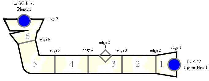
Cell Length (DX):
Cell Volume (VOL): frustum of a cone formula:
Edge FA / HD: \(FA = \pi \, ID^{2}/4\); \(HD = ID\) (at each edge).
CCFL: Wallis correlation at edge 5 (HL–SG inlet elbow interface):
| Parameter | Value |
|---|---|
CBETA |
0.0 (Wallis) |
CCFLM |
0.74 |
CCFLC |
0.38 |
All other edges: LCCFL = 0.
Orientation: edges 1–5 horizontal (\(\theta = 0\), \(GRAV = 0\)); edges 6–7 angled (plant-specific, else 45° → \(GRAV = 0.707\)).
The OTSG HL is more complex — it has a U-bend ("candy cane") at the top. 10 cells / 11 edges for lowered-loop B&W, 12 cells / 13 edges for raised-loop.
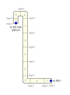
Cell 1 = RPV outlet nozzle; cell 2 = short horizontal segment from SG-inlet-nozzle to first bend; cell 3 = bend region (DX = 2 × \(ID_{HL}\)); cells 4–7 (lowered) or 4–9 (raised) = straight vertical pipe; cells 8–9 (lowered) or 10–11 (raised) = U-bend halves; last cell = SG inlet nozzle + short straight segment.
CCFL: same Wallis model as UTSG (CCFLM = 0.74, CCFLC = 0.38) at the edge closest to the RPV outlet elbow.
Hot Leg Friction Inputs (common structure)¶
| Edge | Feature | KFAC (forward) | KFACR (reverse) |
|---|---|---|---|
| 1 | Core outlet nozzle | \(1.0 \times 10^{-10}\) | \(1.0 \times 10^{-10}\) |
| 2 | Nozzle expansion | Vendor value, else 0.03 (bellmouth inlet, Idelchik Diagram 3-4a) | Vendor value, else 1.00 (discharge into open volume, Idelchik 11-2) |
| 3, 4 | Straight pipe | 0.0 | 0.0 |
| 5 | 45° elbow | \(16 \, f_T\) | \(16 \, f_T\) |
| 6 | Sudden expansion (HL → SG plenum) | \((1-\beta_6^{2})^{2}\) | \(0.5(1-\beta_6^{2})\) |
| 7 | 45° elbow (SG inlet) | \(16 \, f_T\) | \(16 \, f_T\) |
\(\beta_6 = ID_{HL,edge6}/HD_{SGinletPlenum}\). \(f_T\) from Table 1.5-1. \(ICFLG_{edges\,1-7} = 0\).
Hot Leg Initial Conditions¶
| Variable | Value |
|---|---|
| \(P_{cells\,1-6}\) | Plant SS pressure in HL, else nominal RCS pressure |
| \(TL\), \(TV\) | Plant SS temperature, else RV outlet temperature |
| \(ALPN\) | 0.0 (all liquid) |
| \(PA\) | 0.0 |
| \(VL\) | Plant SS liquid velocity, else approximate, else 0.0 |
| \(VV\) | 0.0 |
Hot Leg General Inputs¶
| Input | Value | Notes |
|---|---|---|
ICONC |
Per Section 1.6 | — |
CONC |
Nominal RCS boron (ppm) | — |
IPOW |
0 | — |
EPSW |
Plant value, else \(4.572 \times 10^{-5}\) m | — |
NSIDES |
1 for pressurizer loop (surge-line side junction); 0 for other loops | — |
IACC |
0 (normal pipe) | — |
| Leak paths | 0 | — |
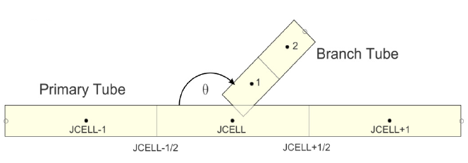
Pressurizer loop side junction (surge-line connection):
| Input | Value |
|---|---|
NCLK |
HL cell at pressurizer surge-line location |
THETA |
Angle between HL pipe (horizontal) and surge line |
IENTRN |
1 (offtake model on — required for horizontally stratified flow during LOCA refill) |
2 — Intermediate Leg¶
7 cells, 8 edges. The IL connects the SG outlet plenum to the RCP suction nozzle, passing through the loop seal. It includes the SG outlet nozzle, a miter bend, a horizontal segment, two 90° bends, and the RCP suction nozzle.
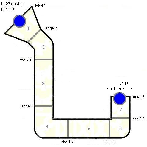
Component Number: Loop# × 100 + 1020.
6 cells, 7 edges for lowered-loop; 2 cells, 3 edges for raised-loop. The IL travels from the bottom SG outlet plenum to the RCP suction through a ~135° curved section (modeled as a single node with manipulated GRAV to preserve both pipe length and net elevation change) plus a straight horizontal segment. Raised-loop plants have a much shorter IL (no straight section).
Intermediate Leg CCFL¶
CCFL is applied at the RCP inlet edge to capture loop-seal clearing phenomena. Uses the Wallis correlation from Bethsy/ROSA-IV/LOFT assessments. Specific CCFL parameters should be consistent with the RCP suction nozzle CCFL model (see Section 3 below).
Intermediate Leg Friction (UTSG — typical)¶
Key loss coefficients include: SG outlet nozzle contraction (edge 1), pipe bends (\(16 \, f_T\) for 45°, \(30 \, f_T\) for 90°), and the expansion into the RCP suction nozzle at the final edge.
Intermediate Leg General Inputs¶
Same pattern as hot leg: IACC = 0, IPOW = 0, NSIDES = 0, EPSW plant or
default, boron per Section 1.6, no leak paths.
3 — Reactor Coolant Pump¶
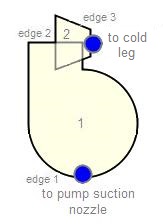
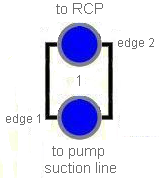
The RCP system consists of two components: 1. A 1-cell PIPE for the pump suction nozzle 2. A 2-cell PUMP (cell 1 = pump body, cell 2 = discharge nozzle)
Component Initialization¶
| Input | Value |
|---|---|
Pump Type (IPMPTY) |
2 — Equation-based rotational speed |
| Hydraulic Diameter | \(ID_{PumpDischarge}\) (overwritten per edge) |
NCELLS |
2 (pump) |
| Total Length | Height from suction nozzle to discharge mid-plane + discharge nozzle length |
| Orientation | Vertical |
CTITLE |
Loop # - RCP (or RCP A/B for 2 pumps per loop) |
NUM |
Loop# × 100 + 1030 (single/A); + 1060 (B) |
Pump Suction Nozzle¶
| Input | Value |
|---|---|
NCELLS |
1 |
| Length | Suction nozzle length |
| HD | \(ID_{PumpSuction}\) |
NUM |
Loop# × 100 + 1025 (single/A); + 1055 (B) |
CCFL at Pump Suction¶
CCFL is applied at the suction edge to capture potential loop-seal clearing countercurrent flow:
| Parameter | Value |
|---|---|
CBETA |
1.0 |
CCFLM |
1.0 |
CCFLC |
1.79 |
Geometry¶
Suction nozzle (1-cell PIPE):
Pump (2-cell PUMP):
- Cell 1: RCP body. \(DX_1 = 2 \times (H_{SuctionOutlet} - H_{DischargeMidplane})\). \(VOL_1\) = manufacturer-provided RCP fluid volume (excluding nozzles).
- Cell 2: Discharge nozzle. \(DX_2 = L_{DischargeNozzle}\). \(VOL_2\) = frustum.
Pump Cell 1 DX
Cell 1 DX must equal twice the elevation change from the pump suction nozzle outlet to the pump discharge mid-plane. Any modeled elevation change across edge 2 is considered to be zero in the evaluation of the momentum equation. If DX₁ is not set correctly, the net elevation change around the loop may become non-zero.
Friction¶
| Edge | Feature | KFAC | KFACR | NFF |
|---|---|---|---|---|
| 1 (suction) | Contraction | \((1-\beta_s^{2})^{2}\) | \(0.5(1-\beta_s^{2})\) | 0 |
| 2 (pump inlet/outlet) | Pump internal | 0.0 | 0.0 | 0 |
| 3 (discharge) | Expansion | \(0.5(1-\beta_d^{2})\) | \((1-\beta_d^{2})^{2}\) | 0 |
\(\beta_s = ID_{suction,edge1}/ID_{suction,edge2}\); \(\beta_d = ID_{discharge,edge3}/HD_{discharge,edge2}\).
NFF at edges 2, 3: set to 1 if \(\beta = 1\) (no area change).
Pump-Specific General Inputs¶
| Input | Value |
|---|---|
IPOW |
0 (frictional heat via PUMPFRICQ NAMELIST variable) |
EPSW |
Plant, else \(4.572 \times 10^{-5}\) m |
NSIDES |
0 |
Reverse Rotation (IRP) |
1 — Yes (allow reverse rotation) |
Degradation (IPM) |
1 — Single+Two-Phase Curves (if OPTION ≠ 3,4); 2 — Head/Torque Two-Phase (if OPTION = 3 or 4) |
Effective MOI (EFFMI) |
Plant-specific pump moment of inertia |
Pump Efficiency (ETA) |
Plant-specific (if not entered, 85% default) |
| Use Alternate Inertia | False |
Pump Curve Option (OPTION) |
0 — User-specified (preferred); 3 — Built-in Bingham; 4 — Built-in Westinghouse; 2 — Built-in LOFT (fallback) |
| Leak paths | 0 |
Speed Trip (IPMPTR) |
Trip ID controlling pump impeller speed |
| Use Pipewall | False — attach HTSTR manually to cells 1 and 2 |
Pump Performance Data¶
All of the following are plant-specific and must be obtained for the RCP being modeled:
Frictional Torque Coefficients:
| Input | Description |
|---|---|
TFR0–TFR3 |
Frictional torque polynomial coefficients |
TFRB |
Torque break speed |
TFRL0–TFRL3 |
Low-speed frictional torque polynomial coefficients |
Rated Values:
| Input | Description |
|---|---|
RHEAD |
Rated head |
RTORK |
Rated torque |
RFLOW |
Rated volumetric flow |
RRHO |
Rated density |
ROMEGA |
Rated speed |
Speed Values:
| Input | Description |
|---|---|
OMEGAN |
Initial speed |
OMGOFF |
Off speed |
ROMGMX |
Maximum speed change |
OMGSCL |
Speed scale factor |
NPMPSD |
Off speed controller |
Homologous Pump Curves:
| Curve | Description |
|---|---|
HSP |
Single-phase homologous head curve |
HTP |
Fully-degraded homologous head curve |
TSP |
Single-phase homologous torque curve |
TTP |
Fully-degraded homologous torque curve |
HDM |
Head degradation multiplier curve |
TDM |
Torque degradation multiplier curve |
4 — Cold Leg¶
The CL is modeled as a PIPE with 6 cells and 7 edges: cell 1 = RCP discharge nozzle connection; cells 2–5 = straight pipe; cell 6 = RPV inlet nozzle. For B&W plants, two small bends may be modeled.

Component Number: Loop# × 100 + 1035.
Cold Leg Friction (typical)¶
| Edge | Feature | KFAC | KFACR | NFF |
|---|---|---|---|---|
| 1 | CL piping from RCP discharge nozzle | \(0.5(1-\beta_1^{2})\) (contraction) + additional loss from RCP discharge direction change | \((1-\beta_1^{2})^{2}\) (expansion) | 0 |
| 2 | Straight pipe | 0.0 | 0.0 | 0 |
| 3–5 | Straight pipe (or bends for B&W) | 0.0 (else \(30 \, f_T\) for 90° bends) | 0.0 (else \(30 \, f_T\)) | 1 |
| 6 | RPV inlet nozzle | \((1-\beta_6^{2})^{2}\) | \(0.5(1-\beta_6^{2})\) | 0 |
| 7 | RPV downcomer area change | Vendor value, else 0.68 (Idelchik Diagram 11-7.2 for 90° discharge into annulus) | Vendor value, else 0.04 (Idelchik Diagram 3-5 for entrance from annulus) | 0 |
\(ICFLG_{edges\,1-7} = 0\).
Cold Leg General Inputs¶
| Input | Value | Notes |
|---|---|---|
ICONC |
Per Section 1.6 | — |
CONC |
Nominal RCS boron (ppm) | — |
IPOW |
0 | — |
EPSW |
Plant value, else \(4.572 \times 10^{-5}\) m | — |
NSIDES |
1 or more (for accumulator discharge line, spray suction line) | — |
IACC |
0 | — |
| Leak paths | 0 | — |
Side-junction connections on the cold leg:
- Accumulator discharge line: connected via side junction;
IENTRN = 0(offtake off — accumulator injects, doesn't extract). - Pressurizer spray suction line (if spray line is on this CL):
IENTRN = 1(offtake on — needed for horizontally stratified flow during LOCA). See Pressurizer Modeling §5.
Geometry Input Summary¶
Table 3.4-1 — UTSG Hot Leg¶
| Node | DX | VOL | Edge | FA | HD | CCFL | GRAV | KFAC | KFACR | NFF | ICFLG |
|---|---|---|---|---|---|---|---|---|---|---|---|
| 1 | \(L_{CoreOutletNozzle}\) | frustum | 1 | \(\pi ID_1^2/4\) | nozzle \(ID_1\) | None | 0.0 | 1.0E-10 | 1.0E-10 | 0 | 0 |
| 2 | \((L_{tot}-DX_1-DX_5-DX_6)/3\) | \(DX_2 \cdot FA_2\) | 2 | \(\pi ID_2^2/4\) | pipe \(ID_2\) | None | 0.0 | vendor or 0.03 | vendor or 1.0 | 0 | 0 |
| 3 | = DX₂ | \(DX_3 \cdot FA_3\) | 3 | \(\pi ID_3^2/4\) | pipe \(ID_3\) | None | 0.0 | 0.0 | 0.0 | 1 | 0 |
| 4 | = DX₂ | \(DX_4 \cdot FA_4\) | 4 | \(\pi ID_4^2/4\) | pipe \(ID_4\) | None | 0.0 | 0.0 | 0.0 | 1 | 0 |
| 5 | \(2 \times d_{SGnozzle \to bend}\) | \(DX_5 \cdot FA_5\) | 5 | \(\pi ID_5^2/4\) | pipe \(ID_5\) | Wallis 0.74/0.38 | 0.0 | \(16 f_T\) | \(16 f_T\) | 1 | 0 |
| 6 | \(L_{SGInletNozzle}\) | frustum | 6 | \(\pi ID_6^2/4\) | pipe \(ID_6\) | None | sin(45°) | \((1-\beta_6^2)^2\) | \(0.5(1-\beta_6^2)\) | 0 | 0 |
| 7 | \(\pi ID_7^2/4\) | nozzle \(ID_7\) | None | sin(45°) | \(16 f_T\) | \(16 f_T\) | 0 | 0 |
\(\beta_6 = ID_{edge6}/HD_{SGInletPlenum}\). \(f_T\) from Table 1.5-1. EPSW plant or \(4.572 \times 10^{-5}\) m.
Table 9.5-1 — RCP (Pump + Suction Nozzle)¶
| Component | Node | DX | VOL | Edge | FA | HD | CCFL | GRAV | KFAC | KFACR | NFF | ICFLG |
|---|---|---|---|---|---|---|---|---|---|---|---|---|
| Suction | 1 | \(L_{SuctionNozzle}\) | frustum | 1 (suction) | \(\pi ID_1^2/4\) | \(ID_1\) | CBETA=1.0, M=1.0, C=1.79 | 1.0 | \((1-\beta_s^2)^2\) | \(0.5(1-\beta_s^2)\) | 0 | 0 |
| 2 (suction) | \(\pi ID_2^2/4\) | \(ID_2\) | None | 1.0 | 0.0 | 0.0 | 0 | 0 | ||||
| Pump | 1 | \(2(H_{suction}-H_{discharge})\) | RCP volume | 2 (pump) | \(\pi ID_2^2/4\) | discharge \(ID_2\) | None | 0.0 | 0.0 | 0.0 | 0 | 0 |
| Pump | 2 | \(L_{DischargeNozzle}\) | frustum | 3 (pump) | \(\pi ID_3^2/4\) | \(ID_3\) | None | 0.0 | \(0.5(1-\beta_d^2)\) | \((1-\beta_d^2)^2\) | 0 | 0 |
\(\beta_s = ID_{edge1}/ID_{edge2}\); \(\beta_d = ID_{edge3}/HD_{edge2}\). NFF at suction edge 2 and discharge edge 3: set to 1 if \(\beta = 1\) (no area change). KFAC/KFACR at pump edges (suction and discharge) are always 0.0.
Modeling Basis (Appendix A — Hot Leg, Intermediate Leg, RCP, Cold Leg)¶
Hot leg (UTSG) — CCFL and pressurizer surge line
The HL is modeled as a straight pipe with nozzles and a miter bend. Two aspects merit attention: (1) the pressurizer surge line connects via a side junction with the offtake model activated (horizontally stratified flow during LOCA refill), and (2) during SBLOCAs, reflux-condensation may lead to CCFL in the HL. The CCFL model is evaluated at the edge closest to the RPV (edge 5) — a horizontal edge where testing shows a hydraulic jump would occur. Downstream edges have flow-area changes, and the effect of area change on the CCFL correlation is not fully understood.
Based on Bethsy, ROSA-IV, and LOFT assessments (Appendix A.26).
Hot leg (OTSG) — candy cane U-bend
The unique characteristic of B&W hot legs is the "candy cane" U-bend at the top. Two symmetrical nodes model the U-bend to ensure balanced gravitational head and reasonable accuracy for liquid spillover phenomena. The exact geometry is not resolved to high detail because stratified flow through the U-bend is not considered critical for most B&W analyses. Raised-loop and lowered-loop configurations differ in the location of the straight-pipe segment (hot leg vs. intermediate leg).
The same CCFL model as UTSG is recommended until further studies confirm applicability.
Intermediate leg — loop seal clearing
The IL includes a straight horizontal pipe segment essential for capturing horizontally-stratified flow regimes. During loop-seal clearing, CCFL may occur at the RCP inlet. The CCFL model (from Bethsy/ROSA-IV/LOFT) is evaluated at the RCP-inlet edge. A separate PIPE for the RCP suction was chosen to enable development of pump "templates" for specific pump models. Modeling the suction as part of the IL is also acceptable. The OTSG IL for lowered-loop B&W plants has a ~135° arc modeled as a single node with manipulated GRAV to preserve pipe length and net elevation change simultaneously.
Reactor coolant pump — approach and curves
The RCP is modeled with IPMPTY = 2 (equation-based rotational speed)
to allow TRACE to compute coastdown from provided inertia data when
the pump trip activates. The pump impeller is allowed reverse rotation
(IRP = 1). For all non-trip conditions, the pump speed is specified
and TRACE computes torque, head, and frictional heat from user-supplied
homologous curves.
Curve selection priority: (1) plant-specific curves if available
(preferred); (2) built-in Bingham curves (OPTION = 3) for Bingham
pumps; (3) built-in Westinghouse curves (OPTION = 4) for
Westinghouse pumps; (4) built-in LOFT curves (OPTION = 2) as the
generic fallback (Semiscale curves are not representative of typical
PWR pumps).
The pipe-wall option is NOT used for the PUMP component — the analyst
must develop and attach HTSTR components manually to cell 1 (pump
internals) and cell 2 (discharge nozzle). Power from pump frictional
heating is handled via the PUMPFRICQ NAMELIST variable.
Cold leg — ECCS connections and downcomer entry
The CL is a straight pipe (or with small bends for B&W plants). Important features include the connection to the accumulator discharge line and (in some loops) the pressurizer spray suction line, both via side junctions. The loss coefficient at the RPV inlet nozzle (edge 7) accounts for the 90° turn from the CL into the downcomer annulus. Default values of 0.68 (forward, Idelchik 11-7.2 for discharge into annulus) and 0.04 (reverse, Idelchik 3-5 for entrance from annulus) are recommended if vendor data is unavailable.
See Appendix A.23 for generic thermal-hydraulic component discussion.
References¶
- TRACE PWR Modeling Guidance, Revision 1, U.S. NRC, February 2015 — Sections 3, 5, 6, 8, 9, 10 and Appendix A.3–A.10.
- TRACE V5.0 Theory Manual, U.S. NRC, ADAMS ML120060218.
- TRACE V5.0 User's Manual, Volume 2: Modeling Guidelines, U.S. NRC, ADAMS ML120060402 (PUMP component, homologous curves).
- Crane Technical Paper No. 410, Flow of Fluids Through Valves, Fittings, and Pipe.
- Idelchik, Handbook of Hydraulic Resistance (Diagrams 3-4a, 3-5, 11-2, 11-7.2).
Related Topics¶
Extracted from TRACE PWR Modeling Guidance, Rev 1 (Feb 2015), §⅗/6/8/9/10 and App. A.3–A.10. No substantive discrepancies were found between the Rev 1 PDF and the corresponding component sources. OTSG intermediate leg details are presented in summary form — refer to the Rev 1 PDF for lowered-loop vs. raised-loop nodalization specifics.