PWR Reactor Vessel Modeling¶
Overview¶
This section provides guidance on how to model a typical PWR reactor pressure vessel (RPV) in TRACE. The guidance applies to the following commercial PWR designs:
- Westinghouse 2-loop PWR
- Westinghouse 3-loop PWR
- Westinghouse 4-loop PWR
- Combustion Engineering 2-loop PWR
- Babcock and Wilcox (B&W) PWR
The RPV is modeled as a 3-D VESSEL component, with auxiliary 1-D PIPE components for thimble tubes and control rod guide tubes (CRGTs), and 1-D VALVE components for B&W reactor-vessel vent valves (RVVVs) where applicable. Before starting, ensure all relevant NAMELIST variables are set per Section 1.2 of the Rev 1 guide.
Source
This page is extracted from TRACE PWR Modeling Guidance, Revision 1 (February 2015), Section 2 — PWR Reactor Pressure Vessel Modeling Guidance and Appendix A.1 — Reactor Pressure Vessel.
Component Function¶
| # | Component | TRACE type | Purpose |
|---|---|---|---|
| 1 | Reactor pressure vessel | VESSEL (VESSTYPE = 0, RPV) |
3-D representation of downcomer, lower plenum, core, upper plenum, and reactor head |
| 2 | Core thimble tubes | PIPE (IACC = 0) |
Alternative axial flow path through unobstructed thimbles in the core |
| 3 | Upper plenum CRGTs | PIPE (IACC = 0) |
Alternative axial flow path through control-rod guide tubes |
| 4 | Reactor vessel vent valves (B&W only) | VALVE (IVTY = 1, flow-area fraction table) |
Steam pathway from upper plenum to downcomer; modeled as zero-cell VALVEs |
Required Inputs¶
Required Plant Data Checklist
- RPV shell geometry (ID, thickness, height, material properties)
- RPV connections (hot/cold leg centerline radial and axial locations)
- Core barrel geometry (ID, thickness, material properties)
- Core baffle geometry (thickness, material properties, baffle plate loss coefficients)
- Thermal shield geometry (ID, thickness, height, location, material properties)
- Reactor vessel vent valve properties — B&W plants only — (seat ID, locations, loss coefficients, fully closed and fully open ΔP)
- Reference core design specs (% obstructed thimbles, number of fuel assemblies, total core flow, % bypass through baffle-barrel region, % total bypass)
- Fuel assembly geometry (active fuel height, number of fuel rods, number of thimble tubes, fuel rod OD, fuel assembly pitch)
- Fuel assembly spacer specifications (locations, loss coefficients)
- Fuel assembly top & bottom nozzle loss coefficients
- Fuel assembly thimble tube geometry (ID, thickness, length, material properties)
- Fuel assembly instrument tube geometry (OD)
- Plate geometry (BSP, LCP, UCP, USP — thickness, locations, flow-hole diameter and count, material properties)
- Incore instrumentation guide tubes (OD, locations) — lower plenum
- Bottom & upper support columns (OD, locations) — lower & upper plena
- Control rod guide tubes (dimensions, thickness, locations) — upper plenum
- Control rod shroud tubes (OD, locations) — upper plenum
- Hot leg nozzle dimensions (OD)
- Steady state RPV fluid conditions (average core temperature, steam dome pressure)
- Steady state pressurizer pressure
1 — Reactor Vessel VESSEL Component¶
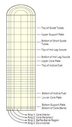
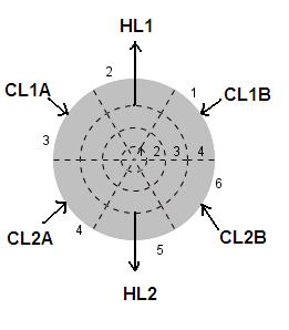
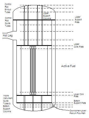
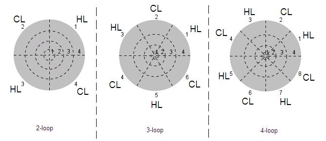
A typical PWR RPV is modeled as a single 3-D VESSEL component. Sample nodalization for a 2-loop plant (2 hot legs / 4 cold legs) is shown below.
Component Initialization¶
| Input | Value |
|---|---|
| Vessel Geometry | Cylindrical |
| Vessel Height | \(H_{ReactorVessel} - 2 \, TH_{ReactorVesselShell}\) |
| Vessel Outer Radius | \(ID_{ReactorVessel}/2\) |
| Total Azimuthal Angle | 360° |
Number of Axial Levels (NASX) |
\(\lceil \dfrac{2 \, H_{ActiveFuel}}{\text{Min spacer spacing}} \rceil + 13\) |
Number of Radial Rings (NRSX) |
4 |
Number of Azimuthal Sectors (NTSX) |
\(N_{ColdLegs} + N_{HotLegs}\) |
| Include Downcomer | Yes |
| Include Core | Yes |
| Boundary Conditions | No flow above and below |
Naming:
CTITLE:Reactor VesselNUM:1000
2 — Core Thimble Tubes / CRGT PIPE Components¶
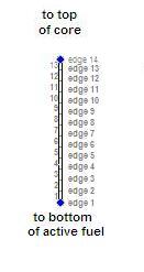
Alternative flow paths through thimbles in the core (between the bottom and
top of the active fuel) and through CRGTs in the upper plenum. Multiple
parallel tubes between the same VESSEL cells are lumped into a single PIPE
component using NPIPES.
Component Initialization¶
| Input | Value |
|---|---|
| Total Length | Guide/thimble tube length |
| Hydraulic Diameter (HD) | \(ID_{GuideTube}\) |
NCELLS (core thimble tubes) |
\(N_{Z} - 11\) |
NCELLS (CRGTs) |
Number of axial levels between planned upper and lower CRGT locations |
NPIPES (core thimble tubes) |
(Number of unobstructed thimble tubes in the ring of interest) ÷ (number of azimuthal sectors) |
NPIPES (CRGTs) |
(Number of CRGTs in the ring of interest) ÷ (number of azimuthal sectors) |
| Orientation | Vertical |
Naming:
CTITLE:Core Thimble Tube – Ring # Sector #orControl Rod Guide Tube – Ring # Sector #NUM:900–915for core thimble tubes;920–935for CRGTs
Connection Points (per ring × azimuthal sector)¶
- Core thimble tubes (Ring L = 1 to 2; Sector M = 1 to \(N_\theta\)):
- Inlet: Ring L, Sector M, Level 4, Face 2 (positive axial)
- Outlet: Ring L, Sector M, Level \((N_Z - 7)\), Face \(-2\) (negative axial)
- CRGTs (Ring L = 1 to 2; Sector M = 1 to \(N_\theta\)):
- Inlet: Ring L, Sector M, Level X, Face 2 (positive axial)
- Outlet: Ring L, Sector M, Level Y, Face \(-2\) (negative axial)
- Levels X and Y correspond to the levels whose upper face is the connection point for the lower and upper CRGT openings.
3 — RPV Nodalization¶
Axial Levels¶
The cell heights for each axial level are defined relative to the Bottom Support Plate (BSP), Lower Core Plate (LCP), Upper Core Plate (UCP), Upper Support Plate (USP), and Reactor Head (RH) elevations:
| Axial Level(s) | Region | Height |
|---|---|---|
| 1 | Lower Plenum (LP) below DC flow path | \(E_{DC\,bottom} - E_{Vessel\,bottom}\) |
| 2–3 | Flow path from DC to LP | \(\dfrac{E_{BSP} - E_{DC\,bottom}}{2}\) |
| 4 | BSP to LCP | \(E_{LCP} - E_{BSP}\) |
| 5 | LCP to bottom of active fuel | \(E_{BottomActiveFuel} - E_{LCP}\) |
| 6 to (\(N_Z - 8\)) | Active fuel (uniform) | \(\dfrac{H_{ActiveFuel}}{N_Z - 12}\) |
| (\(N_Z - 7\)) | Top of active fuel to UCP | As indicated |
| (\(N_Z - 6\)) | UCP to bottom of HL nozzle | As indicated |
| (\(N_Z - 5\)) | Bottom to top of HL nozzle | \(OD_{HLNozzle}\) |
| (\(N_Z - 4\)) to (\(N_Z - 3\)) | Top of HL nozzle to USP | \(\dfrac{E_{USP} - E_{TopHLNozzle}}{2}\) |
| (\(N_Z - 2\)) | USP to RH | \(E_{RH\,bottom} - E_{USP}\) |
| (\(N_Z - 1\)) | Lower RH | \(E_{Ring3\,top} - E_{RH\,bottom}\) |
| \(N_Z\) | Upper RH | \(E_{RV\,top} - E_{Ring3\,top}\) |
Table 2.3-1 — RPV axial nodalization. \(N_Z\) = total number of axial levels.
Radial Rings¶
Determine the number of fuel assemblies in the interior group (Ring 1) and periphery group (Ring 2). If plant power-distribution data is unavailable, use the typical assembly counts below as a starting point:
| Plant Vendor | Total Assemblies | Periphery Assemblies |
|---|---|---|
| Westinghouse | 121 | 48 |
| Westinghouse | 157 | 56 |
| Westinghouse | 193 | 56 |
| Combustion Engineering | 133 | 44 |
| Combustion Engineering | 177 | 56 |
| Combustion Engineering | 204 | 60 |
| Combustion Engineering | 217 | 60 |
| Combustion Engineering | 241 | 64 |
| Babcock & Wilcox | 171 | 56 |
Table 2.3-2 — Typical fuel-assembly allocation for radial nodalization.
The radial-ring radii are computed as:
| Ring | Region | Radius |
|---|---|---|
| 1 | Core interior | \(\sqrt{\dfrac{N_{InteriorAssemblies} \, Pitch_{Assembly}^{2}}{\pi}}\) |
| 2 | Core periphery | \(\sqrt{\dfrac{\text{Core Baffle Interior Area}}{\pi}}\) |
| 3 | Baffle-barrel bypass | \(\dfrac{ID_{CoreBarrel}}{2}\) |
| 4 | Downcomer | \(\dfrac{ID_{RV}}{2}\) |
Table 2.3-3 — RPV radial nodalization.
Azimuthal Sectors¶
Each azimuthal sector boundary is placed midway between the angles where adjacent legs meet the vessel. The angle for each sector \(i\) is:
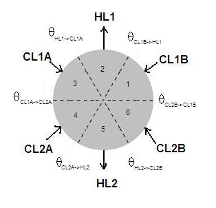
If detailed leg locations are unknown, use uniform 90° / 60° / 45° sectors for 4-, 6-, or 8-leg configurations respectively.
4 — Geometry Inputs¶
The following internal structures are explicitly considered for volume, flow area, and HD calculations:
- Core barrel
- Core baffle
- Thermal shield
- Bottom support plate (BSP), Lower core plate (LCP), Upper core plate (UCP), Upper support plate (USP)
- Fuel assemblies, control rods, control rod guide tubes (CRGTs), control rod shroud tubes (CRSTs)
- Thimble tubes, instrument tubes
- Bottom and upper support columns (BSCs, USCs)
- Incore instrumentation guide tubes (IIGTs)
- Fuel assembly top and bottom nozzles
Structures not explicitly considered (analyst should use detailed plant volume breakdowns where possible to correct):
- Fuel assembly spacers (loss coefficients ARE applied)
- Diffuser/flow mixer plates, baffle support plates
- CRGT lower portions with horizontal-flow openings
- Alignment pins, support ledges, internal protrusions
Internal-Structure Volume Coefficients (per unit axial height)¶
The following structure-specific \(VOL/Z_{i,j}\) values are used in the cell-volume formulas of Table 2.3-7. \(Z_{i,j}\) is the average axial height of structure \(j\) in the \(i^{th}\) axial level.
| Structure | \(VOL/Z_{i,j}\) |
|---|---|
| Bottom support column (BSC) | \(\dfrac{\pi}{4} \, OD_{BSC}^{2}\) |
| Incore instrument guide tube (IIGT) | \(\dfrac{\pi}{4} \, OD_{IIGT}^{2}\) |
| Core barrel | \(\pi \, TH_{CoreBarrel} \, (ID_{CoreBarrel} + TH_{CoreBarrel})\) |
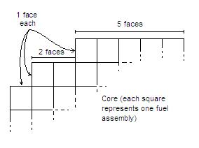
| Core baffle | \(N_{FuelAssemblyFacesOnPeriphery} \times TH_{Baffle} \times Pitch_{FuelAssembly}\) |
| Thermal shield | \(\pi \, TH_{ThermalShield} \, (ID_{ThermalShield} + TH_{ThermalShield})\) |
| Upper support column (USC) | \(\dfrac{\pi}{4} \, OD_{USC}^{2}\) |
| Control rod guide tube (CRGT) | \(OuterWidth_{CRGT}^{2}\) |
| Control rod shroud tube (CRST) | \(\dfrac{\pi}{4} \, OD_{CRST}^{2}\) |
| Fuel assembly | \(N_{FuelRods/Assy} \, \dfrac{\pi}{4} OD_{FuelRod}^{2} + N_{ThimbleTubes/Assy} \, \dfrac{\pi}{4} OD_{ThimbleTube}^{2} + \dfrac{\pi}{4} OD_{InstrumentTube}^{2}\) |
| Support/core plates (BSP, LCP, UCP, USP) flow area, per ring | \(\sum N_{holes} \, \dfrac{\pi}{4} \, ID_{holes}^{2}\) |
Table 2.3-5 — RPV internal-structure volumes (per unit axial height).
Flow Area Allocation Across Rings¶
For the BSP/USP, allocation is based on radial position:
| Plate | Ring | \(\%_{Plate,Ring_i}\) |
|---|---|---|
| BSP/USP | 1 | \(R_1^2 / R_3^2\) |
| BSP/USP | 2 | \((R_2^2 - R_1^2)/R_3^2\) |
| BSP/USP | 3 | \(1 - R_2^2/R_3^2\) |
| LCP/UCP | 1 | \(\dfrac{(1-\%_{Bypass})\,(N_{InteriorAssy} \, Pitch_{Assy}^{2})}{\pi R_2^2}\) |
| LCP/UCP | 2 | \(\dfrac{(1-\%_{Bypass})\,(N_{PeripheryAssy} \, Pitch_{Assy}^{2})}{\pi R_2^2}\) |
| LCP/UCP | 3 | \(\%_{Bypass,Barrel-Baffle}\) |
Table 2.3-6 — Flow-area fractional allocation for RPV plates.
Cell Volume Calculation¶
The RPV is approximated as a cylinder with semi-ellipsoid caps. Volumes for each cell are given as \(VOL/\theta^*\), where \(\theta^* = \theta_i / 360°\) for the \(i^{th}\) azimuthal sector. Multiply the table value by \(\theta^*\) to obtain the volume for each azimuthal sector.
Table 2.3-7 — Per-cell volume formulas (click to expand)
The volume of each cell in the RPV depends on the axial level and ring. The full set of formulas is reproduced below in summary form.
Axial Level 1 (LP below DC flow path):
- Ring 1: \(\dfrac{2\pi R_4^2}{3}(Z_2+Z_1)\left[1-(1-R_1^2/R_4^2)^{3/2}\right] - \pi R_1^2 Z_2 - N_{BSCs,Ring1} \cdot VOL_{i,BSC} - N_{IIGTs,Ring1} \cdot VOL_{i,IIGT}\)
- Ring 2: \(\dfrac{2\pi R_4^2}{3}(Z_2+Z_1)\left[(1-R_1^2/R_4^2)^{3/2}-(1-R_2^2/R_4^2)^{3/2}\right] - \pi (R_2^2-R_1^2) Z_2 - N_{BSCs,Ring2} \cdot VOL_{i,BSC} - N_{IIGTs,Ring2} \cdot VOL_{i,IIGT}\)
- Ring 3: \(\dfrac{2\pi R_4^2}{3}(Z_2+Z_1)\left[(1-R_2^2/R_4^2)^{3/2}-(1-R_3^2/R_4^2)^{3/2}\right] - \pi (R_3^2-R_2^2) Z_2\)
- Ring 4: \(0.0\)
Axial Level 2 (DC-to-LP flow path, lower):
- Rings 1–3: \(\pi (\Delta R^2) Z_2\) minus structure deductions
- Ring 4: \(\dfrac{2\pi R_4^2}{3}(Z_2+Z_1)(1-R_3^2/R_4^2)^{3/2}\)
Axial Level 3 (DC-to-LP flow path, upper):
- Rings 1–3: \(\pi (\Delta R^2) Z_3\) minus structure deductions
- Ring 4: \(\pi (R_4^2-R_3^2) Z_3\) minus core barrel volume
Axial Level 4 (BSP to LCP):
- Each ring: \((Z_4 - TH_{BSP}) \pi (\Delta R^2) + \%_{BSP,Ring_i} TH_{BSP} FA_{BSP}\) minus support-column / IIGT deductions
Axial Level 5 (LCP to bottom of active fuel):
- Ring 1: \(N_{InteriorAssy}\left[(Z_5 - TH_{LCP}) Pitch_{Assy}^{2} - VOL_{FuelBottomNozzle}\right] + \%_{LCP,Ring1} TH_{LCP} FA_{LCP}\)
- Ring 2: \(N_{PeripheryAssy}\left[(Z_5 - TH_{LCP}) Pitch_{Assy}^{2} - VOL_{FuelBottomNozzle}\right] + \%_{LCP,Ring2} TH_{LCP} FA_{LCP}\)
- Ring 3: \((Z_5 - TH_{LCP}) \pi (R_3^2-R_2^2) + \%_{LCP,Ring3} TH_{LCP} FA_{LCP}\)
- Ring 4: \(Z_5 \pi (R_4^2-R_3^2) - VOL_{4,ThermalShield} - VOL_{4,CoreBarrel}\)
Axial Levels 6 to (\(N_Z - 8\)) (active fuel region):
- Ring 1: \(N_{InteriorAssy}\left(Z_i Pitch_{Assy}^{2} - VOL_{FuelAssembly}\right)\)
- Ring 2: \(N_{PeripheryAssy}\left(Z_i Pitch_{Assy}^{2} - VOL_{FuelAssembly}\right)\)
- Ring 3: \(Z_i \pi (R_3^2-R_2^2) - VOL_{i,CoreBaffle}\)
- Ring 4: \(Z_i \pi (R_4^2-R_3^2) - VOL_{i,ThermalShield} - VOL_{i,CoreBarrel}\)
Axial Level (\(N_Z - 7\)) (top of active fuel to UCP):
- Like Level 5 but using \(VOL_{FuelTopNozzle}\) instead of \(VOL_{FuelBottomNozzle}\)
Axial Level (\(N_Z - 6\)) (UCP to bottom of HL nozzle):
- Each ring: \((Z_i - TH_{UCP}) \pi (\Delta R^2) + \%_{UCP,Ring_i} TH_{UCP} FA_{UCP}\) minus USC and CRGT deductions
Higher levels (HL nozzle, USP, lower/upper RH) follow similar patterns using semi-ellipsoid geometry. Refer to Rev 1 §2.3 Table 2.3-7 for the full uncondensed expressions, including the upper RH cap region which accommodates the upper-plenum-to-downcomer leakage flow path geometry.
Cell Flow Areas¶
Cell flow areas follow analogous per-ring/per-axial-level formulas to the volumes. Key principles:
- Axial flow areas at each face are calculated from the cell volume divided by cell height (with structure deductions).
- Radial flow areas at the boundaries between rings use \(2 \pi R_n Z_i\) minus the cross-sections of structures crossing the boundary.
- Azimuthal flow areas are zero at the edges adjacent to the hot leg nozzle penetrations through the downcomer (artificial barrier — see Bases).
- Ring 4 azimuthal flow areas at the HL nozzle level account for the reduced annulus area due to the nozzle penetration.
Cell Hydraulic Diameter¶
\(HD\) is computed as \(4 \, A_f / P_{wet}\) for each cell. For the active fuel region in Rings 1–2, the wetted perimeter includes fuel rods, thimble tubes, and instrument tubes. For the downcomer, \(HD = 2 \, (R_4 - R_3)\). Plate flow paths use \(HD = 4 \, A_{hole} / P_{hole}\) averaged over the holes.
Hot Leg Penetration Treatment¶
At the axial level containing the HL nozzle:
- The cylindrical volume of the nozzle is deducted from the appropriate Ring 4 azimuthal sector cell volume.
- The axial flow area in that sector is reduced to account for the nozzle blockage.
- The azimuthal flow area at the edges adjacent to the HL nozzle volumes is set to 0.0 to prevent artificial mixing across the nozzle (this is an intentional barrier — see Bases).
- Loss coefficients for the contraction/expansion at the HL nozzle are small enough to be neglected at the total downcomer azimuthal flow area level.
5 — Friction Inputs¶
Initially, all KFAC values are 0.0. Liquid and vapor K-factor arrays must both be specified — use the same values in both arrays unless otherwise directed. Recommended non-zero KFAC values:
| Axial Level(s) | Sector(s) | Ring(s) | Edge | Area / Direction Change | KFAC |
|---|---|---|---|---|---|
| 2–3 | All | 3 | Radial | DC-to-LP 180° turn | Forward: \(k_{180°AnnularTurn}\) from Idelchik Diagram 6-28 (configurations w/o dividers, fairings, or guide vanes). Default: 10.0 if DC flow-path height / barrel ID ≥ 0.25. Reverse: \(k_{180°AnnularTurn}\) from Diagram 6-27. Default: 9.5. |
| 1–4 and (\(N_Z - 6\)) to \(N_Z\) | All | 1–2 | Radial & Azimuthal | Flow ⊥ to BSCs/IIGTs/USCs/CRGTs/CRSTs | Forward = Reverse = \(k_{tubebank}\) from Diagram 12-28 (staggered banks). Often ≈ 0 due to large pitch-to-diameter ratio. |
| 6 to (\(N_Z - 8\)) | All | 1–2 | Radial (Ring 1 only) & Azimuthal | Flow ⊥ to fuel rods | \(k_{tubebank}\) from Diagram 12-29 (in-line). Default 0.70 for typical pitch/diameter ≈ 1.33. |
| 6 to (\(N_Z - 8\)) | All | 1–2 | Axial | Fuel spacers | \(k_{spacers}\) from manufacturer. Default 2.0 if unknown. Tune to match measured core ΔP — recommend SNAP Numerics. |
| 5, (\(N_Z - 7\)) | All | 1–2 | Axial | Fuel bottom & top nozzle losses | \(k_{nozzles}\) from manufacturer. Default 2.0 if unknown. Tune with spacers to match core ΔP. |
| 6 to (\(N_Z - 8\)) | All | 3 | Axial | Baffle support plates | \(k_{CoreBafflePlates}\) from manufacturer. Default 4.0 if unknown. Tune to match core ΔP. |
| (\(N_Z - 5\)), (\(N_Z - 6\)) | All | 4 | Axial | Area change due to HL obstruction of DC | Forward at (\(N_Z - 5\)) and Reverse at (\(N_Z - 6\)): \(0.5(1 - FA_{(N_z-5)}/FA_{(N_z-4)})\) (contraction). Forward at (\(N_Z - 6\)) and Reverse at (\(N_Z - 5\)): \((1 - FA_{(N_z-5)}/FA_{(N_z-4)})^2\) (expansion). |
| 3 | All | 1–3 | Axial | Area change due to BSP | \(k_{contraction} + k_{expansion} = 0.5(1 - FA_2/FA_1) + (1 - FA_2/FA_1)^2\) |
| 4 | All | 1–3 | Axial | Area change due to LCP | \(k_{contraction} = 0.5(1 - FA_3/FA_1)\) |
| (\(N_Z - 7\)) | All | 1–3 | Axial | UCP | \(k_{expansion} = (1 - FA_{(N_z-7)}/FA_{(N_z-6)})^2\) |
| (\(N_Z - 3\)) | All | 1–3 | Axial | USP | \(0.5(1 - FA_{(N_z-3)}/FA_{(N_z-4)}) + (1 - FA_{(N_z-3)}/FA_{(N_z-4)})^2\) |
Table 2.3-14 — KFAC inputs for the RPV. Reference 5 = Idelchik Handbook of Hydraulic Resistance.
6 — Initial Condition Inputs¶
Initial liquid velocities are set assuming uniform flow from the cold legs through the downcomer and core to the hot legs. Edges not listed are 0.0. TRACE will refine the flow distribution during steady-state initialization.
| Axial Level(s) | Sector(s) | Ring(s) | Edge | \(VL\) |
|---|---|---|---|---|
| 2 | All | 4 | Axial | \(\dfrac{-\dot{m}_{Total}}{\rho_{coolant} \cdot 2 \cdot FA_i / \theta^*}\) |
| 3 to (\(N_Z - 7\)) | All | 4 | Axial | \(\dfrac{-\dot{m}_{Total}}{\rho_{coolant} \cdot FA_i / \theta^*}\) |
| (\(N_Z - 6\)) | All | 4 | Axial | \(\dfrac{-\dot{m}_{Total}}{\rho_{coolant} \sum_{All\,sectors} FA_i}\) |
| 2 | All | 1–3 | Axial | \(\dfrac{\dot{m}_{Total}}{\rho_{coolant} \cdot 2 \cdot \sum_{Rings\,1-3} FA_i / \theta^*}\) |
| 3–4, (\(N_Z - 6\)) | All | 1–3 | Axial | \(\dfrac{\dot{m}_{Total}}{\rho_{coolant} \sum_{Rings\,1-3} FA_i / \theta^*}\) |
| 5 to (\(N_Z - 7\)) | All | 1–2 | Axial | \(\dfrac{\dot{m}_{Total} (1 - \%_{Bypass})}{\rho_{coolant} \sum_{Rings\,1-2} FA_i / \theta^*}\) |
| 5 to (\(N_Z - 7\)) | All | 3 | Axial | \(\dfrac{\dot{m}_{Total} \cdot \%_{Bypass,Baffle-Barrel}}{\rho_{coolant} \cdot FA_i / \theta^*}\) |
| 2,3 | All | 1 | Radial | \(\dfrac{-\dot{m}_{Total} (R_1^2/R_3^2)}{\rho_{coolant} \cdot FA_i / \theta^*}\) |
| 2,3 | All | 2 | Radial | \(\dfrac{-\dot{m}_{Total} (R_2^2/R_3^2)}{\rho_{coolant} \cdot FA_i / \theta^*}\) |
| 2,3 | All | 3 | Radial | \(\dfrac{-\dot{m}_{Total}}{\rho_{coolant} \cdot 2 \cdot FA_i / \theta^*}\) |
| (\(N_Z - 6\)) | All | 1 | Radial | \(\dfrac{\dot{m}_{Total} (R_1^2/R_3^2)}{\rho_{coolant} \cdot FA_i / \theta^*}\) |
| (\(N_Z - 6\)) | All | 2 | Radial | \(\dfrac{\dot{m}_{Total} (R_2^2/R_3^2)}{\rho_{coolant} \cdot FA_i / \theta^*}\) |
Table 2.3-15 — Liquid velocity inputs for the RPV.
Where:
- \(\dot{m}_{Total}\) = total core flow
- \(\rho_{coolant}\) = coolant density at nominal average core temperature and pressurizer pressure
- \(FA_i\) = flow area of cell \(i\)
- \(\theta^* = \theta_j / 360°\) for azimuthal sector \(j\)
- \(\%_{Bypass}\) = core bypass through baffle-barrel region
Vapor Velocity: \(VV_{AllEdges} = 0.0\) (no vapor expected in steady-state RPV).
7 — Special Model Option Inputs¶
Wall Friction Multipliers¶
Liquid (WFMFL) and vapor (WFMFV) wall-friction multipliers are not used
unless MWFL/MWFV NAMELIST variables are activated — not recommended.
Orifice Option¶
Activate at all edges in the downcomer-to-lower-plenum flow path:
- Radial face 3 at axial levels 2 & 3, all azimuthal sectors
- Axial faces 2 & 3 in Ring 4, all azimuthal sectors
- All azimuthal faces in Ring 4 for axial levels 2 & 3
Orifice option = No (unchecked) for all other cells.
Abrupt Area Change¶
Not recommended — minor losses are accounted for via KFAC inputs. Abrupt area change = No for all cells.
CCFL Model¶
CCFL is activated at the upper core plate (UCP). The model depends on UCP hole diameter:
| Hole diameter | Model | CBETA |
CCFLM (slope) |
CCFLC (constant) |
|---|---|---|---|---|
| ≤ 2.86 cm | "N" (Bankoff) | \(-1.0\) | 1.07 | 0.00433 |
| > 2.86 cm | "M" (Wallis) | 0.0 | 1.22 | 0.88 |
LCCFL = applicable model "N" or "M" at axial level \((N_Z - 6)\), Rings 1–3,
all azimuthal sectors. LCCFL = 0 at all other cells.
8 — Core Reflood Heating Inputs¶
The core reflood heating model is essential for accurate quench-front tracking and thermal-hydraulic behavior during reflood after dryout. Activate the model:
- Use Reflood = True (
RFLDINPUT = 1)
Reflood Planar Cell Inputs¶
| Planar Cell | Unheated Fraction | Average Heat Structure |
|---|---|---|
| 1 | 0.0 | Fresh Fuel Rods – Ring 1 Sector 1 |
| 2 | 0.0 | Fresh Fuel Rods – Ring 1 Sector 2 |
| ... | ... | ... |
| \(N_\theta\) | 0.0 | Fresh Fuel Rods – Ring 1 Sector \(N_\theta\) |
| \(N_\theta + 1\) | 0.0 | Fresh Fuel Rods – Ring 2 Sector 1 |
| ... | ... | ... |
| \(2 N_\theta\) | 0.0 | Fresh Fuel Rods – Ring 2 Sector \(N_\theta\) |
| \(2 N_\theta + 1\) to \(4 N_\theta\) | 1.0 | Not specified |
Table 2.3-16 — Reflooding inputs for the RPV.
Fresh-fuel assumption
The fresh-fuel association is based on the typical case where fresh fuel is the limiting fuel at end-of-cycle (EOC) due to highest power levels. If this assumption does not hold for a particular analysis, the analyst should re-associate the heat structure accordingly.
9 — General Inputs¶
| Input | Value | Notes |
|---|---|---|
Wall roughness (EPSW) |
Plant value, else \(1.524 \times 10^{-6}\) m | Drawn-pipe roughness |
Vessel type (VESSTYPE) |
0 — RPV |
Drywell type uses specialized condensation model — not for RPV |
Boundary condition option (IVSSBF) |
0 — No flow above or below |
All connections are via 1-D component faces |
Solute option (ICONC) |
Per Section 1.6 | — |
Boron concentration (CONC) |
Nominal SS primary system value (ppm) | If ICONC = 1 |
Vessel elevation (SHELV) |
0.0 | IELV = 1 modeling not recommended |
Disable 3-D level tracking (NOLT) |
False | Level tracking IS used in DC and barrel-baffle regions via ILEV array |
Vent valves (NVENT, NVVTB) |
0, "Use Vent Valve Table" = False | Internal RVVV model NOT used — model RVVVs as separate VALVE components |
| Spacer grid locations | Not used by TRACE | Leave blank |
Internal RVVV model is not recommended
The VESSEL component contains an internal RVVV model, but it is not recommended for use due to known issues. RVVVs should be modeled as separate zero-cell VALVE components (see Section 10). The analyst should ensure that no RVVV data is input on the VESSEL component itself.
Boundary Interface Inputs (used for graphical output)¶
| Variable | Value |
|---|---|
| Includes Downcomer | True |
| Downcomer Upper Interface | \((N_Z - 3)\) |
| Downcomer Lower Interface | 3 |
| Downcomer Inner Radius | 3 |
| Includes Core | True |
| Core Upper Interface | \((N_Z - 8)\) |
| Core Lower Interface | 5 |
| Core Outer Radius | 2 |
| Lower Support Plate | 4 |
| Upper Support Plate | \((N_Z - 7)\) |
| Upper-head Support Plate | \((N_Z - 3)\) |
10 — Reactor Vessel Vent Valves (B&W only)¶
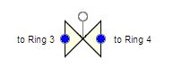
For B&W plants with RVVVs, model each RVVV (or each azimuthal sector containing RVVVs) as a separate zero-cell VALVE component connected between Ring 3 and Ring 4 of the VESSEL at the appropriate axial level.
Component Initialization¶
| Input | Value |
|---|---|
| Hydraulic Diameter | \(ID_{RVVVSeat}\) |
NCELLS |
0 (zero-cell) |
| Orientation | Horizontal |
CTITLE |
RVVV – Azimuthal Sector # |
NUM |
940–947 |
Connection Points (per azimuthal sector \(N\), axial level \(M\))¶
- Inlet: Ring 3, Sector \(N\), Level \(M\), positive radial face
- Outlet: Ring 4, Sector \(N\), Level \(M\), negative radial face
Geometry¶
\(N_{RVVVs}\) may be a non-integer (e.g., 1.5 for 1½ RVVVs split between sectors).
Orientation: Horizontal (\(\theta = 0\), \(GRAV = 0\)).
Initial Conditions¶
\(VL_{edge\,1} = VV_{edge\,1} = 0.0\) (no flow expected at SS).
Friction¶
| Input | Value |
|---|---|
NFF_edge1 |
0 (negligible friction; all losses applied via KFAC) |
KFAC_edge1 |
Manufacturer forward loss coefficient for fully open valve. Default 2.78 if unknown. |
KFACR_edge1 |
Same as KFAC_edge1 |
ICFLG_edge1 |
1 (choked flow expected) |
If \(C_v\) is provided instead of K, convert per Crane TP-410 page 2-10.
Valve Inputs¶
| Input | Value | Notes |
|---|---|---|
IVTY |
1 — Flow Area Fraction Table |
— |
IPOW |
0 | Fluid power not modeled |
EPSW |
Plant value, else \(4.572 \times 10^{-5}\) m | — |
IVPS |
Edge 1 of 1 | — |
IVTYOV |
0 — Flow Area Fraction/sec |
— |
INTLOSSOFF |
1 — Off |
Internal loss model has known errors with explicit KFAC |
RVMX, RVOV |
\(1 / t_{open}\), \(1 / t_{close}\) | — |
FMINOV, FMAXOV |
0.0 / 1.0 | — |
AVLVE |
\(FA_{edge\,1}\) | — |
HVLVE |
\(HD_{edge\,1}\) | — |
FAVLVE, XPOS |
0.0 | Initially closed |
VTB1 |
[(-1e20, 0.0); (max fully-closed ΔP, 0.0); (min fully-open ΔP, 1.0); (1e20, 1.0)] |
Linear opening curve, positive independent variable |
VRF |
Not used | — |
| Leak paths | 0 | — |
IVSV |
Signal-variable ID for ΔP across valve (Ring 3 − Ring 4 pressure subtract) | — |
IVTROV |
0 | Override trip not used |
Required signal variables and control block:
- A "Subtract" control block (Type 54) computes ΔP = \(P_{Ring3} - P_{Ring4}\)
- Two volumetric signal variables read \(P_{Ring3}\) and \(P_{Ring4}\) at the appropriate sector and axial level (
ISVN = 21, parameter type "Pressure")
Flow Capacity Verification¶
After building the RVVV components, verify they achieve the correct flow rate at the appropriate rated pressure(s) per Section 1.8 of the Rev 1 guide.
11 — Core Thimble / CRGT PIPE Modeling¶
Detailed modeling of the lumped thimble-tube and CRGT PIPE components.
Geometry¶
For both core thimble tubes and CRGTs:
- Cell length (\(DX\)): uniform, equal to the corresponding RPV VESSEL axial-level height. The PIPE cells map 1-to-1 with the VESSEL axial levels they span.
- Cell volume (\(VOL\)): \(N_{tubes\,per\,PIPE} \cdot \pi/4 \cdot ID_{tube}^{2} \cdot DX_i\) (where \(N_{tubes\,per\,PIPE}\) =
NPIPES). - Edge flow area (\(FA\)): \(\pi/4 \cdot ID_{tube}^{2} \cdot N_{tubes}\)
- Edge HD: \(ID_{tube}\)
- CCFL: \(LCCFL = 0\) (CCFL not expected in lumped tubes)
- Orientation: Vertical, \(\theta = +1.571\) rad (upward), \(GRAV = +1.0\)
Initial Conditions¶
| Variable | Value |
|---|---|
| \(P\) | Plant SS pressure, else nominal RCS pressure |
| \(TL\), \(TV\) | Plant SS temperatures, else average core temperature |
| \(ALPN\) | 0.0 (all liquid) |
| \(PA\) | 0.0 |
| \(VL\) | \(\dot{m}_{ThimbleBypass} / (\rho \cdot FA \cdot N_{tubes})\), or 0 |
| \(VV\) | 0.0 |
Friction¶
- \(NFF\): 0 at inlet/outlet edges (sudden contraction/expansion); 1 at interior edges
- \(KFAC_{inlet}\) = \(0.5(1 - \beta^{2})\) where \(\beta = ID_{tube}/HD_{adjacentVesselCell}\) (sudden contraction)
- \(KFAC_{outlet}\) = \((1 - \beta^{2})^{2}\) (sudden expansion)
- \(KFACR\) = mirror of KFAC
- \(ICFLG = 0\)
General Inputs¶
| Input | Value |
|---|---|
ICONC |
Per Section 1.6 |
CONC |
Nominal RCS boron (ppm) |
IPOW |
0 |
EPSW |
Plant value, else \(4.572 \times 10^{-5}\) m |
NSIDES |
0 |
IACC |
0 (normal pipe) |
| Leak paths | 0 |
| Pipe wall & wall power | Per Section 1.7 |
The thimble tubes and CRGTs are connected back to the VESSEL using side-junction-style connections at their inlet and outlet faces (see Connection Points in Section 2 above).
Modeling Basis (Appendix A.1 — Reactor Pressure Vessel)¶
RPV azimuthal segmentation
The azimuthal segmentation is based on hot- and cold-leg positions, because this is the main source of azimuthal variation in flow entering/leaving the RPV. The TRACE model can then capture asymmetries from breaks, single-loop heat-transfer deficiencies, or other typical initiating events. These asymmetries can produce significant azimuthal flow gradients, fluid temperature distributions, and other property variations in the downcomer.
Why 4 radial rings
The outermost ring is necessary to segregate the downcomer from the inner vessel region. The inner two rings reflect the typical PWR core's significant power difference between interior and periphery — flat power-distribution targets in modern fuel management can no longer be maintained at the periphery because of neutron leakage. The fourth ring (between core barrel and core baffle) was historically modeled with 1-D PIPE components, but NRC staff found this approach increased numeric instability and computation time. Use of a separate 3-D ring is more cells but significantly more stable.
Generic guidance assumes that "all fuel with at least a corner on the periphery" is assigned to Ring 2. Power-distribution review shows that fuel with at least one edge on the periphery is clearly at lower power, while fuel with only a corner on the periphery sits between interior and periphery levels.
Axial level placement
Axial levels are placed to coincide with flow-area obstructions (plates) or with locations where 1-D components (thimble tubes, CRGTs) must connect. Hot- and cold-leg connection levels are set based on the HL nozzle dimensions. The lower and upper plena and active fuel are each subdivided for distinct reasons:
- Lower plenum (4 levels): the bottom-most level shares no edges with Ring 4 — flow into the LP from the downcomer does not carry significant axial momentum. This is a consequence of the coarse nodalization and the formulation of TRACE's 3-D momentum equations. UPTF assessment results show this approach improves the timing of RPV refill/reflood. The Rev 1 guidance uses three levels for the DC-to-LP region (the original UPTF model used two), because the momentum transfer problem produces a larger irrecoverable pressure drop than expected, and subdividing into two levels improved (but did not eliminate) the discrepancy.
- Active fuel: subdivided so that edges aligned with fuel-spacer locations are separated by at least one non-spacer edge. Cell heights are set to half the minimum spacer pitch. This produces uniform nodalization through the active fuel and gives better axial gradient detail in void fraction and liquid subcooling — especially near the quench front during reflood. It also accommodates intermediate flow mixing grids in modern fuel designs with minimal effort.
- Upper plenum (2 levels): avoids modeling a large fluid volume with a single axial level. There is less flow/heat-transfer activity here, but a void bubble may form during LOCA — adequate nodalization is needed to capture the steam transfer from core to upper plenum and the resulting downflow of liquid.
RPV downcomer modeling
The downcomer is modeled as the majority of Ring 4. Coolant flows from cold legs into the annulus, and a loss coefficient is applied at the cold-leg nozzle outlet. However, due to issues with TRACE's momentum-equation formulation, the calculated pressure drop may be greater than reality. If this is the case, the loss coefficient may need to be reduced (but not eliminated — SNAP will flag a flow-area mismatch otherwise).
At the same axial level as the cold legs, the hot-leg nozzle passes through the downcomer. The volume change in the affected azimuthal sectors is approximated by removing a cylinder with circular area = HL nozzle OD and thickness = downcomer thickness. The axial flow area in those sectors is reduced, and a zero flow area is set at the azimuthal edges adjacent to the volumes containing the HL nozzle. This is an artificial barrier to azimuthal mixing — but it maintains the barrier to mixing that the HL nozzles physically pose to flow from the cold legs.
There is a known leakage path between the downcomer and upper plenum through the crack between the HL nozzle and the core barrel. NRC studies show this leakage can reduce peak clad temperature (PCT) during certain LOCA scenarios, but it is difficult to quantify and is generally not included in plant models.
Lower plenum and lower-plenum plates
Real PWRs may have non-flat (hemispherical) bottom support plates, but the modeling guidance treats them as flat — TRACE cannot accurately model these geometries without significant nodalization increases. The impact is small for most transients because the BSP's main hydraulic role is as a flow obstruction (captured via flow area and KFAC at the top of axial level 3). This assumption needs re-evaluation for transients where lower-plenum mixing is important.
The first three LP levels are treated as an ellipsoid for geometry calculation; the fourth level is a cylinder. All plates are modeled in terms of reductions to liquid volume, flow area, and HD; KFAC is applied at flow-area changes. Plates are not modeled as heat structures because their stored energy is small and hydraulic transport dominates over heat transfer.
Lower-plenum support columns and instrumentation tubes are handled flexibly — the equations assume sparse distribution (no significant overlap from edge-of-view perspective). If detailed information is unavailable, these structures can be neglected as long as the fluid volumes are correct.
Reactor core
The core (Rings 1–2 between LCP and UCP) is modeled as fuel assemblies + coolant. The lattice geometry is computed from assembly pitch and the cylinders making up fuel rods, thimble tubes, and instrument tubes. Flow is permitted in all directions except radially through the outer edge of Ring 2 (where the core baffle is). A simplifying assumption: azimuthal and radial flow areas equal the cylinder flow areas multiplied by the open-flow fraction along a single row of fuel rods.
Spacer KFACs are preferably from the facility, but defaults are provided. In all cases the analyst will need to tune spacer KFACs to obtain the correct steady-state core ΔP. Top and bottom nozzle geometries are too complex for general formulas — only their volume and KFAC effects are modeled. If spacer KFACs are tuned, nozzle KFACs are adjusted proportionately.
Thimble tubes are modeled as 1-D PIPE components for the alternative flow path through unobstructed thimbles. The analyst is responsible for determining which tubes are open. Thimble tubes are assumed to be cylinders extending from the top of the bottom nozzle to the top of the top nozzle. Instrument tubes are neglected for convenience — their fluid volume is small relative to the core. Default KFACs assume sudden contraction/expansion at thimble entry/exit but may be adjusted if the bypass flow percentage through thimbles is known.
Baffle-barrel bypass region (Ring 3)
The core baffle is converted into an equivalent cylinder for volume calculation (the volume is preserved, but the geometry is homogenized azimuthally). The baffle support plates are not modeled explicitly, but their flow resistance is captured via large KFAC at the same elevations as the core spacers. The exact plate locations are not important hydraulically, but a realistic pressure gradient is desired for TRACE-PARCS coupling (because pressure variation feeds into PARCS cross-sections via fluid properties).
No flow occurs across the core barrel or core baffle, but baffle-plate leakage produces a specified bypass flow through this region. If the facility provides a combined "bypass flow including baffle-barrel and thimble tubes", the analyst can split the bypass between the two paths (preferred) or assume the thimble KFACs are accurate and tune only the baffle-barrel KFACs to match total bypass.
A small fraction of total RV energy deposition occurs in the baffle-barrel region from neutron leakage and moderator collisions — but TRACE cannot model direct moderator heating in volumes not coupled to fuel heat structures, so this energy is ignored (effectively assigned to the core).
Upper plenum
The upper plenum (Rings 1–3 between UCP and the top of the RPV shell, excluding the Ring 4 downcomer) contains the upper support plate, the upper support columns, and the CRGTs. The top two axial levels are modeled as semi-ellipsoid; the others are cylindrical.
All plates are modeled in terms of volume/area/HD reductions with KFAC, but not as heat structures. The UCP includes a CCFL model using values from the literature supported by Bethsy/ROSA-IV/LOFT test assessments (Appendix A.26).
Upper-plenum support columns are handled with the same sparse-overlap assumption as the lower plenum. CRGTs may be modeled as 1-D PIPE components to capture the alternative flow path from the top of the core (or above, if the lower portion of the CRGT has horizontal-flow openings) to above the USP. CRSTs surround the control-rod shaft near the upper RPV head; the portion between the top of the CRGTs and the RPV shell is included, with an assumption that the control rods extend the full length of the CRGTs. The control-rod "spider" is ignored — this considerably simplifies the geometry with minimal impact on free volume.
B&W reactor vessel vent valves (RVVVs)
Babcock and Wilcox plants include RVVVs in the RPV. During some transients, steam flows from the upper plenum through the RVVVs to the downcomer where it can condense. RVVVs are spring-loaded valves that open based on differential pressure.
TRACE includes an internal RVVV model in the VESSEL component, but the model is currently considered defective. Subsequent improvements led to the ability to use zero-volume VALVE components, which is now the recommended approach. The guidance presents a typical valve that opens/closes linearly between upper and lower ΔP setpoints, consistent with known RVVV operation.
Initial conditions, level tracking, and reflood model
Initial conditions throughout the RPV are generically specified using nominal pressurizer pressure and average core temperature for cells where detailed ICs are unavailable. Initial velocities assume the total steady-state flow travels uniformly from the cold legs through the downcomer and core, exiting at the HL level. Flow circulating into the reactor head via the upper-plenum-to-downcomer leakage is small and can be initialized to zero without significantly increasing convergence time.
Level tracking is explicitly activated for the RPV because a well-defined water level normally exists in the downcomer and bypass regions during some phases of LOCA transients.
The reflood heating model is activated, with each radial/azimuthal cell associated with the heat structure for fresh fuel (which is typically the limiting fuel at EOC). The peak cladding temperature during LOCA analyses is strongly affected by reflood, so this is a safety-significant choice. A footnote warns the analyst when the fresh-fuel assumption may not hold, with an item in the LOCA transient checklist as a reminder.
See Appendix A.23 of the Rev 1 guide for generic thermal-hydraulic component discussion.
References¶
- TRACE PWR Modeling Guidance, Revision 1, U.S. NRC, February 2015 — Section 2 and Appendix A.1.
- TRACE V5.0 Theory Manual, U.S. NRC, ADAMS ML120060218.
- TRACE V5.0 User's Manual, Volume 2: Modeling Guidelines, U.S. NRC, ADAMS ML120060402 (VESSEL component, reflood heating model).
- Crane Technical Paper No. 410, Flow of Fluids Through Valves, Fittings, and Pipe.
- Idelchik, Handbook of Hydraulic Resistance (Diagrams 6-27, 6-28 for 180° annular turn; 12-28, 12-29 for tube-bank cross flow).
- UPTF (Upper Plenum Test Facility) assessment reports.
Related Topics¶
- Primary Loop Modeling
- Steam Generator Modeling
- Pressurizer Modeling
- Accumulator Modeling
- Containment Modeling
Extracted from TRACE PWR Modeling Guidance, Rev 1 (Feb 2015), §2 and App. A.1. The most complex per-cell volume formulas (Table 2.3-7, all 11 axial levels × 4 rings) are summarized in a collapsible block; refer to the Rev 1 PDF for the full uncondensed expressions. No substantive discrepancies were found between the Rev 1 PDF and the corresponding component source (Historical-Rev_1/Vessel.docx).