PWR Reactor Power & Kinetics¶
Source
Rev 1 Modeling Guidance, §18 — Reactor Power Guidance; Appendix A.18 — Power Bases.
Overview¶
This section provides guidance on modeling PWR reactor core power in TRACE using the POWER component with point kinetics (IRPWTY=4). This guidance is for stand-alone TRACE calculations without PARCS coupling. The guidance is applicable to Westinghouse ⅔/4-loop, CE 2-loop, and B&W PWRs.
Point Kinetics Applicability
The analyst should verify that the point kinetics model is appropriate for the transient being analyzed. This approach is generally acceptable if no highly localized core power response characteristics are expected. For transients requiring spatial kinetics, TRACE-PARCS coupled calculations may be necessary.
Required Inputs¶
- Hot Full Power (HFP) level and initial power level
- Initial reactivity and scram reactivity insertion curve
- Scram trip signals
- Core characteristics (reload fraction, cycle length)
- Axial power shape and radial power distribution
- Decay heat data (if not using ANS-94 tables)
- Reactivity coefficients (Doppler, moderator temperature/density, boron)
- Kinetics parameters (delayed neutron data, prompt neutron lifetime)
Component Setup¶
- Component Number: 1999
- Power Option (IRPWTY): 4 (PK with constant reactivity + table input)
- Include Reactivity Feedback: True (adds 10 → IRPWTY=14)
- Target Component Type (CHANPOW): 0 (Heat Structures)
General Inputs¶
| Parameter | Value | Notes |
|---|---|---|
| RPOWRI | HFP level (watts) | Or other initial power for specific analyses |
| REACT | 0.0 | Zero initial reactivity (steady state) |
| TNEUT | 2.0 × 10⁻⁵ s | Prompt neutron lifetime (use facility-specific if available) |
| PROMHEAT | 0.026 | Prompt direct moderator heating fraction |
| DECAHEAT | 0.0 | Decay DMH (negligible, may be neglected) |
| WTBYPASS | 0.0 | Bypass DMH (not applicable to PWRs) |
| RANS | 1.0 | Decay heat multiplier (1.0 for best-estimate) |
| RPWOFF | −1.0 × 10¹⁹ | Off reactivity (ensure shutdown if trip resets) |
| RRPWMX | 10²⁰ | Max reactivity change rate (no restriction) |
| RPWSCL | 1.0 | Reactivity scale factor |
| EXTSOU | 0.0 | No external power source |
| NRTS | 100 | Edit frequency |
Powered Components¶
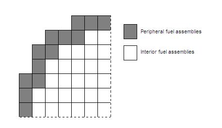
Power fractions (CPOWR) for each fuel rod HTSTR are determined by averaging the relative assembly power for all assemblies in Rings 1 and 2:
Scram Reactivity Table (RPWTBR)¶
- Independent Variable (IRPWSV) = problem time signal
- Independent Variable Form = negative (time since trip)
- Controller Trip (IRPWTR) = reactor scram trip number
Generic US PWR scram reactivity curve (if facility-specific data unavailable):
| Time after scram (s) | Inserted reactivity (Δk/k) |
|---|---|
| 0.1 | 0.0 |
| 0.4 | −3.515 × 10⁻⁴ |
| 0.8 | −7.23 × 10⁻⁴ |
| 1.2 | −3.615 × 10⁻³ |
| 1.6 | −1.3737 × 10⁻² |
| 2.0 | −6.0 × 10⁻² |
| 2.4 | −7.23 × 10⁻² |
| ∞ | −7.23 × 10⁻² |
Rod Insertion Timing
If only position-vs-reactivity data is available, convert to time using: d = ½·C·g·t² where d = insertion distance, g = 9.81 m/s², C = adjustment constant. STS rod insertion times: B&W = 1.66 s to 75% insertion; CE = 3.1 s to full insertion; W = 2.2 s to full insertion.
Fission Inputs (Decay Heat)¶
| Parameter | Value | Notes |
|---|---|---|
| Q235 | 203.78 MeV | U-235 energy per fission |
| Q239 | 209.88 MeV | Pu-239 energy per fission |
| Q238 | 204.32 MeV | U-238 energy per fission |
| QAVG | 205.43 (BOC) / 206.01 (EOC) MeV | Average energy per fission |
| R239PF | 0.55 | U-239 atoms per fission |
| FISPHI | 0.713 | Fissions per initial atom |
| FP235 | 0.801 (BOC) / 0.647 (EOC) | U-235 power fraction |
| FP238 | 0.0319 (BOC) / 0.0425 (EOC) | U-238 power fraction |
Power History & Decay Heat Standard¶
- NDHX = −94 (ANS-94 with U-239/Np-239 decay)
- NHIST = 2 (power history table)
- PHIST = [(0.0, Core Power); (BUtavg, Core Power)]
Average burnup time for typical 18-month cycle with ⅓ reload:
Decay Heat Overestimate
Using an infinite power history (default) instead of a calculated BUtavg may lead to non-trivial overestimates of decay heat levels. Always input a power history table.
Power Shape Inputs¶
Axial Power Shape¶
| Parameter | Value |
|---|---|
| IPWRAD | 0 (1-D axial table) |
| IPWDEP | 0 (defined by IZPWZ) |
| NZPWI | 1 (trapezoidal approximation) |
| NZPWZ | Number of data pairs |
Generic Chopped Cosine Axial Power Profile (click to expand)
| Z-coordinate (fraction of active fuel height) | Relative Power |
|---|---|
| 0.0 | 0.33574 |
| 1/16 | 0.54938 |
| ⅛ | 0.74803 |
| 3/16 | 0.92628 |
| ¼ | 1.07927 |
| 5/16 | 1.20281 |
| ⅜ | 1.29354 |
| 7/16 | 1.34899 |
| ½ | 1.36765 |
| 9/16 | 1.34899 |
| ⅝ | 1.29354 |
| 11/16 | 1.20281 |
| ¾ | 1.07927 |
| 13/16 | 0.92628 |
| ⅞ | 0.74803 |
| 15/16 | 0.54938 |
| 1.0 | 0.33574 |
For a specific axial peaking factor, solve iteratively: 2θ/(2·sin θ) = desired peaking factor, then ZPWTB(z) = A·cos[θ·(2z−1)/Hfuel]
Radial Power Shape¶
- RDPWR = [1.0, 1.0, 1.0, 1.0, 1.0, 0.0, 0.0, 0.0] (uniform in fuel, zero in clad/gap)
Reactivity Coefficient Inputs¶
| Coefficient | TRACE Variable | Index | Recommended Unit Index |
|---|---|---|---|
| Fuel temperature (Doppler) | RCTF | IFBTYP1 = 0 (avg fuel temp) | — |
| Moderator temperature | RCTC | IFBTYP2 = 0 (void-weighted mod temp) | — |
| Moderator density | RCAL | IFBTYP3 = 1 (void-weighted mod density) | — |
| Boron | RCBM | — | ISNOTB = 0; solute units = −2 (ppm) |
Moderator Coefficient Conversion
If the facility provides a moderator temperature coefficient (dρ/dT), convert to density coefficient: dρ/∂d = (dρ/dT) / (∂d/dT). Apply the temperature coefficient up to Tsat; apply the void coefficient above Tsat.
Generic US PWR coefficients (if no facility data available):
- Coolant temperature: −1.6667 × 10⁻⁵ K⁻¹
- Fuel temperature (Doppler): −9.4444 × 10⁻⁶ K⁻¹
- Void reactivity: −1.85 × 10⁻²
Delayed Neutron Data¶
6-Group Delayed Neutron Data (click to expand)
BOC:
| Group | β (fraction) | λ (s⁻¹) |
|---|---|---|
| 1 | 1.978 × 10⁻⁴ | 0.0129 |
| 2 | 1.200 × 10⁻³ | 0.0311 |
| 3 | 1.150 × 10⁻³ | 0.134 |
| 4 | 2.070 × 10⁻³ | 0.331 |
| 5 | 5.900 × 10⁻⁴ | 1.26 |
| 6 | 2.307 × 10⁻⁴ | 3.21 |
EOC:
| Group | β (fraction) | λ (s⁻¹) |
|---|---|---|
| 1 | 1.598 × 10⁻⁴ | 0.0129 |
| 2 | 9.692 × 10⁻⁴ | 0.0311 |
| 3 | 9.292 × 10⁻⁴ | 0.134 |
| 4 | 1.672 × 10⁻³ | 0.331 |
| 5 | 4.766 × 10⁻⁴ | 1.26 |
| 6 | 1.864 × 10⁻⁴ | 3.21 |
Scram Trip Signals¶
Typical reactor protection system signals by vendor:
| B&W | CE | Westinghouse |
|---|---|---|
| Nuclear overpower | Variable high power | High power range neutron flux |
| RCS high outlet temp | High power rate of change | Overtemperature ΔT |
| RCS high/low pressure | Low reactor coolant flow | Overpower ΔT |
| Reactor bldg high P | Low pressurizer pressure | Low/high pressurizer pressure |
| RCP to power | High containment pressure | High pressurizer water level |
| Main turbine trip | Low SG pressure/level | Low reactor coolant flow |
| Loss of MFW pumps | Loss of load | Low-low SG water level |
| Steam generator ΔP | Turbine trip/TSV closure |
Cross-References¶
- Heat Structures — Fuel rod HTSTR components powered by this POWER
- Control Systems — Scram trip logic
- Reactor Vessel — Core thermal-hydraulics
This page faithfully extracts reactor power guidance from Rev 1 §18. The POWER component uses IRPWTY=14 (point kinetics with reactivity feedback + scram table). Key inputs include ANS-94 decay heat with power history, chopped cosine axial profile, 6-group delayed neutrons, and moderator density reactivity coefficients converted from facility-provided temperature coefficients.